
Baler gate linkage and latch structur

a latch structure and gate technology, applied in the field of baler, can solve the problems of increasing difficulty in maintaining shipping and road transportation heights within acceptable ranges, increasing difficulty in servicing the bale chamber area or replenishing the wrap mechanism of the baler, especially in the chassis-mounted baler, etc., to improve the processing height reduction feature, improve the baler structure, and improve the latch structure

Active Publication Date: 2005-04-21
DEERE & CO
View PDF14 Cites 3 Cited by
  • Summary
  • Abstract
  • Description
  • Claims
  • Application Information

AI Technical Summary

Benefits of technology

[0004] It is therefore an object of the present invention to provide an improved on-board cotton handling system that overcomes most or all of the aforementioned problems. It is another object to provide such a system having an improved processor height reduction feature. It is a further object to provide an improved gate latch structure for a baler of the type utilized with an on-board processing system.
[0005] It is yet another object of the present invention to provide an improved baler structure particularly useful with an on-board cotton harvester module building system. It is a further object to provide such a structure having improved service accessibility and improved transport and shipping configurations.
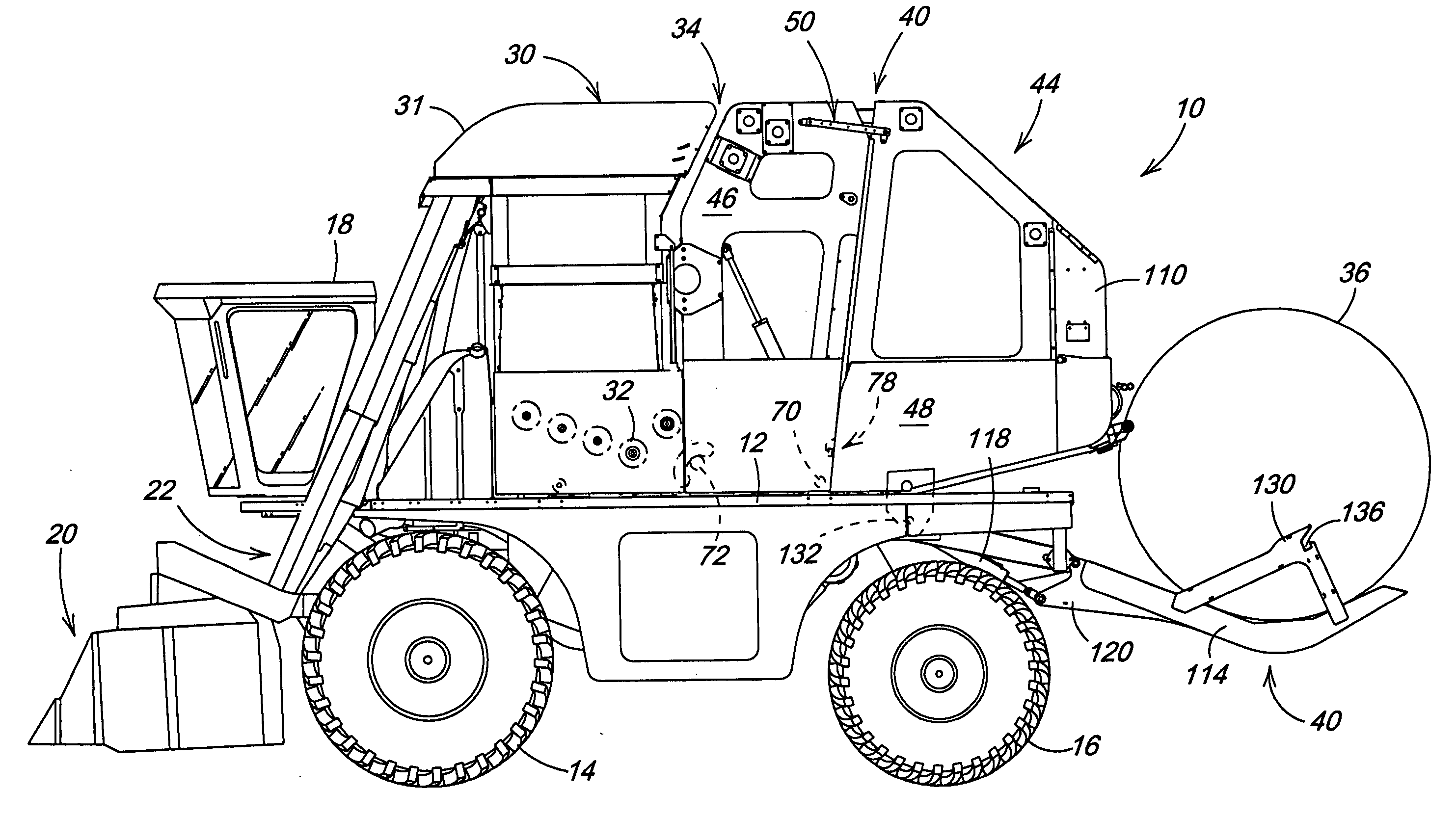
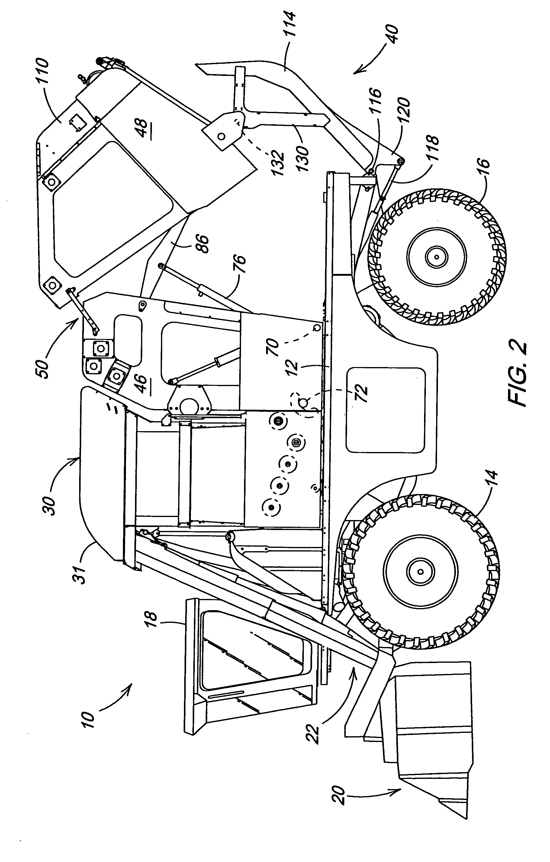
[0006] A chassis-mounted round baler particularly useful with an on-board cotton module building system includes a bale release gate frame section connected to a forward frame section by a four bar or similar control linkage. The linkage generates a baler gate path that allows the folding of the baler into both field transport and shipping configurations while maintaining desirable operating, transport and shipping heights typical of many current cotton pickers. The linkage cooperates with a bale handler on the cotton picker which assists in the folding function and supports the gate in the transport and shipping configurations.
[0007] The gate linkage also incorporates a self latching feature the eliminates the weight, cost and complexity of a separate latching mechanism. The baler gate linkage permits a small vertical movement of the gate as the gate cylinders are operated. When the cylinders are first extended to raise the gate, an initial vertical movement lifts the gate slightly to release a gate latch member from a forward frame member. As the cylinders are retracted to move the gate closed, an opposite vertical motion at the end of the closing path reengages the gate latch from the forward frame member.
[0008] The four bar linkage also allows the gate center of gravity to be positioned such that the gate will stay in a fully opened position without positive pressure in the actuators that open the gate. The linkage and the ability to fold the baler into lower transport and shipping positions allows bale wrap to be put in the machine from the ground and makes service points on the baler easier to access. The gate interacts with the bale handler to provide a stop for the baler gate when the baler gate is placed into a cradle on the handler. The gate latches to the cradle and is moved to a reduced height transport or shipping position with downward movement of the handler. The gate cylinders can be operated in a float mode while the gate is latched to the handler.

Problems solved by technology

The formed bale is relatively large, and designing the bale-forming chamber to maintain a satisfactory harvester shipping and transport height has been a continuing source of difficulty.
As the capacity of a harvester increases, the problems with maintaining shipping and road transport heights within acceptable ranges become more acute.
In addition, servicing the bale chamber area or replenishing the wrap mechanism of the baler, particularly in a chassis-mounted baler, becomes more challenging because of the increased height of the unit above the ground.
Such mechanisms, which may include cylinder operated locks or complicated linkages which have to be adjusted and which add to the cost and complexity of the baling system.

Method used


Image

  • Baler gate linkage and latch structur
  • Baler gate linkage and latch structur
  • Baler gate linkage and latch structur

Examples


Embodiment Construction

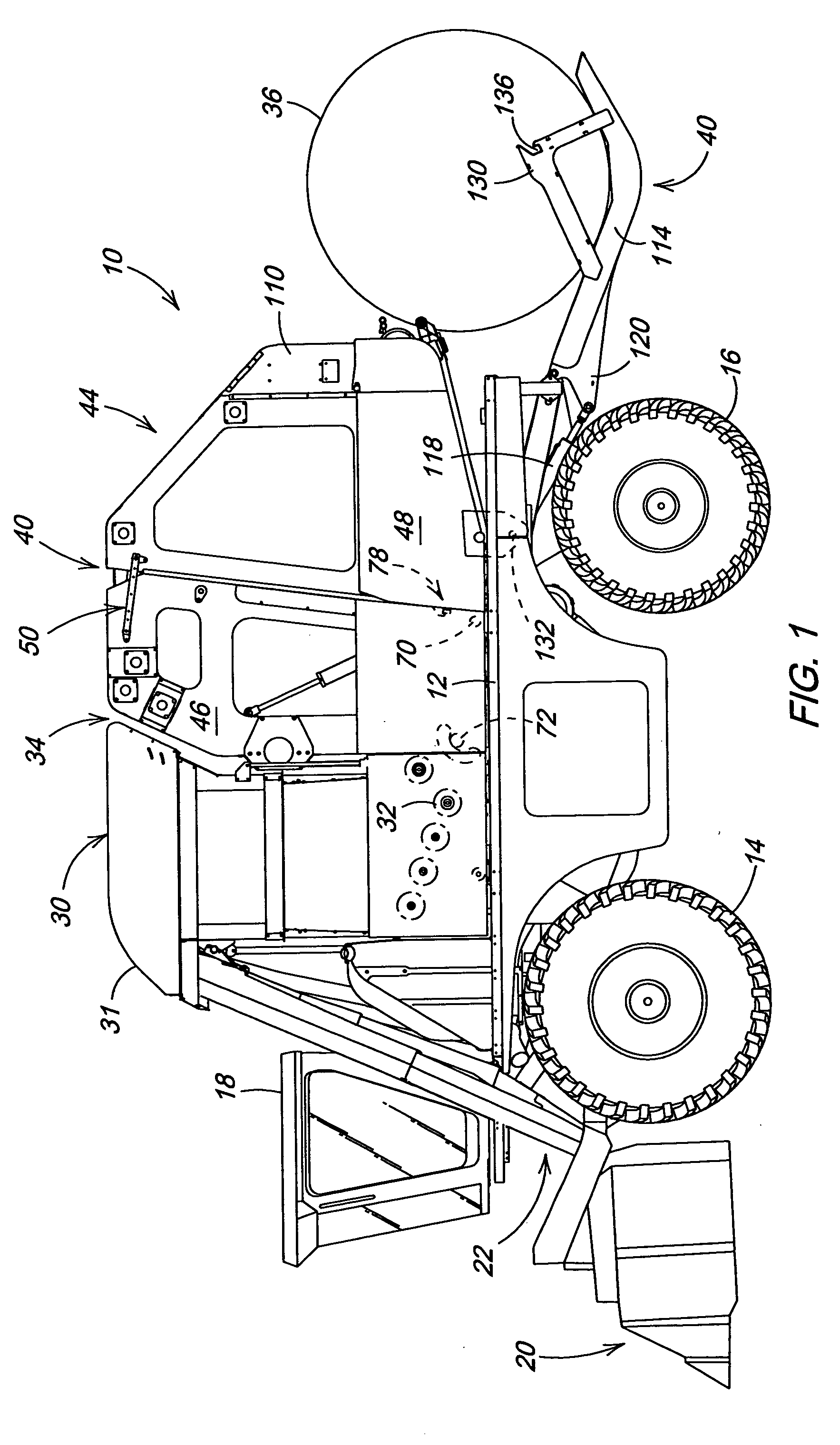
[0016] Referring to FIG. 1 therein is shown a cotton harvester 10 having a main frame 12 supported for movement by forward drive wheels 14 and rear steerable wheels 16. A cab 18 is supported at the front end of the main frame 12 above forwardly mounted harvesting structure indicated at 20 which removes cotton from plants and directs the removed cotton into an air duct system 22.

[0017] An upright telescoping accumulator system 30 with an upper inlet structure 31 and a metering floor 32 is supported on the frame 12 behind the cab 18 for receiving the cotton from the air duct system 22. A processor or module builder 34 is supported rearwardly of the accumulator system 30. The accumulator system 30 stores cotton as necessary, and the metering floor 32 distributes the cotton to the module builder 34 which first forms a mat of material and then rolls the mat into a compact bale or module 36. The accumulator and processor system with the exception of the linkage and locking structure desc...


PUM


Abstract

A chassis-mounted round baler particularly useful with an on-board cotton module building system includes a bale release gate frame section connected to a forward frame section by a four bar linkage to define a gate path that allows the folding of the baler into both field transport and shipping configurations while maintaining desirable operating, transport and shipping heights. The gate linkage incorporates a self latching feature wherein a small vertical movement of the gate as the gate cylinders are operated releases a gate latch member from a forward frame member during gate opening and reengages the gate latch with the forward frame member during closing. The gate interacts with the bale handler to provide a stop for the baler gate when the baler gate is placed into a cradle on the handler.

Description

FIELD OF THE INVENTION [0001] The present invention relates generally to bale forming structures and, more specifically, to a baler of the type utilized with a cotton harvester to provide a cotton module directly on the harvester. BACKGROUND OF THE INVENTION [0002] Cotton harvesters having on-board module forming structure such as described in commonly assigned U.S. Pat. No. 6,421,996 provide a compact bale or module directly on the harvester to reduce the amount of support equipment needed in the field and minimize harvester idle time during offloading. The on-board processing structure includes a bale handling system for moving a large formed bale rearwardly to prepare the bale chamber for a second bale with little or no harvester down time. The formed bale is relatively large, and designing the bale-forming chamber to maintain a satisfactory harvester shipping and transport height has been a continuing source of difficulty. The system shown in the aforementioned U.S. Pat. No. 6,4...

Claims


Application Information

Patent Timeline
IPC IPC(8): A01D46/08A01F15/07
CPCA01F15/07A01D46/084
Inventor FOX, JEFFREY ROBERTPEARSON, MICHAEL LEEBARES, ROBERT MATTHEW
Owner DEERE & CO
Learn More