
Abrasive product, method of making and using the same, and apparatus for making the same

a technology for abrasive products and abrasives, which is applied in the field of flexible abrasive products, can solve the problems of patterned abrasive coatings, abrasive granules having a specified pattern on the backing,

Inactive Publication Date: 2005-04-21
3M INNOVATIVE PROPERTIES CO
View PDF62 Cites 96 Cited by
  • Summary
  • Abstract
  • Description
  • Claims
  • Application Information

AI Technical Summary

Benefits of technology

The method produces abrasive products with consistent high cut levels throughout their life, reducing waste and operational costs while maintaining a smooth surface finish, effectively bridging the performance gap between coated and surface conditioning products.

Problems solved by technology

The mold has patterned cavities therein which result in the abrasive granules having a specified pattern on the backing.
The presence of the grid results in a patterned abrasive coating.

Method used


Image

  • Abrasive product, method of making and using the same, and apparatus for making the same
  • Abrasive product, method of making and using the same, and apparatus for making the same
  • Abrasive product, method of making and using the same, and apparatus for making the same

Examples


example 1

[0136] The particulate curable binder-abrasive particle mixture was formed by mixing 15 g (0.033 lb) of Powder A with 85 g (0.19 lb) of Mineral B. The particulate curable binder-abrasive particle mixture was thoroughly blended by shaking in a closed container for a period of time as determined by visual inspection. The primer mixture was a blend of 60 parts resin Powder C and 40 parts resin Powder A. The primer mixture was thoroughly blended by shaking in a closed container for a period of approximately 30 seconds. A 200 mm by 300 mm (8 in×12 in) piece of Backing A that had been dyed and stretched in its' manufacture was placed on a metal plate of about the same size. A thin coating of the primer mixture was applied to Backing A by evenly spreading a small quantity of the primer mixture with a metal blade. The application of the primer mixture with this method yielded a layer approximately 0.05 to 0.15 mm (0.002 to 0.006 in) thick after a subsequent curing step. A perforated metal s...

examples 2-9

[0139] The method of preparation for these examples was similar to the procedure followed in Example 1 with the changes to the composition and cure time identified in Table 3.

example 10

[0140] The preparation of this example was the same as the procedure followed in Example 1 except that 3 drops of a wetting agent (obtained under the trade designation “SANTICIZER 8” from Ferro Corporation, Cleveland, Ohio) was added to the 15 g (0.033 lb) of Powder B and thoroughly mixed, prior to the addition of Mineral A when making the particulate curable binder-abrasive particle mixture.

TABLE 2Example #12345678910Cure Time4224734434(Minutes @204° C.(400° F.))Resin15%17.5% 15%20%40%Powder AResin15%Powder BResin15%Powder DResin15%Powder EResin1.5%Powder FResin17.5%Powder GResin10.5% Powder HPowder I2.5%Mineral A85%Mineral B85%85%85%82.5% 88%Mineral C 80%85%Mineral D80%Mineral E60%


PUM

PropertyMeasurementUnit
abrasive particle sizeaaaaaaaaaa
particle sizeaaaaaaaaaa
temperatureaaaaaaaaaa

Abstract

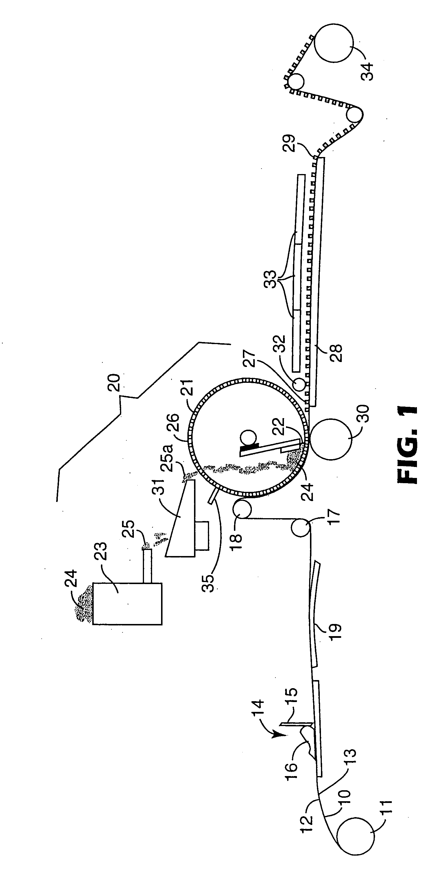
The invention provides a method and apparatus for making an abrasive product comprising providing a substantially horizontally deployed flexible backing having a first surface bearing an at least partially cured primer coating and an opposite second surface; providing a dry flowable particle mixture comprising abrasive particles and particulate curable binder material; depositing a plurality of temporary shaped structures comprised of said particle mixture on the at least partially cured primer coating of the first surface of the backing; softening said particulate curable binder material to provide adhesion between adjacent abrasive particles; and curing the softened particulate curable binder material to convert said temporary shaped structures into permanent shaped structures and cure the at least partially cured primer coating on the first surface of the backing. The invention also provides an abrasive product made by the method.

Description

FIELD OF THE INVENTION [0001] The present invention relates generally to flexible abrasive products which include a backing which bears shaped abrasive structures, a method of making and using the same, and an apparatus for making the same. BACKGROUND ART [0002] Abrasive products are available in any of a variety of types, each generally being designed for specific applications and no particular type providing a universal abrading tool for all applications. The various types of abrasive products include, for example, coated abrasives, bonded abrasives, and low density or nonwoven abrasive products (sometimes called surface conditioning products). Coated abrasives typically comprise abrasive granules generally uniformly distributed over and adhered to the surface of a flexible backing. Bonded abrasives, a typical example of which is a grinding wheel, generally comprises abrasive material rigidly consolidated together in a mass in the form of a rotatable annulus or other shapes such a...

Claims


Application Information

Patent Timeline
Patent Type & Authority Applications(United States)
IPC IPC(8): B24D3/00B24D3/02B24D3/28B24D9/04B24D11/00B24D11/06
CPCB24D3/002B24D11/00B24D3/28B24D2203/00B24D11/001B24D18/0009
Inventor WELYGAN, DENNIS G.CHESLEY, JASON A.MOREN, LOUIS S.
Owner 3M INNOVATIVE PROPERTIES CO
Learn More