Supply interface unit for direct current power pooling

a technology of direct current and power pooling, which is applied in the direction of non-electric variable control, process and machine control, instruments, etc., can solve the problems of shortening the life of the power supply, and reducing the power supply life of the dedicated additional power supply. , to achieve the effect of reducing the power need of the electrical load

Inactive Publication Date: 2005-04-14
NEVERMORE SOLUTIONS
View PDF7 Cites 14 Cited by
  • Summary
  • Abstract
  • Description
  • Claims
  • Application Information

AI Technical Summary

Benefits of technology

[0106] In one embodiment the operating at least one node comprises: operating a plurality of nodes in a pre-assigned operating mode in response to the pooling controller utilizing the group address. In one further embodiment the operating a plurality of node

Problems solved by technology

The combination of modules each comprising an on-board power supply often leads to a less than optimum situation, in which the on-board power supply of some modules are operating at low utilization, while the on-board power supply of other modules are approaching or have reached maximum utilization.
This increase in temperature leads to a shortened life for the power supply.
Furthermore, in prior art systems, a dedicated additional power supply will typically be initially underutilized, and will only experience optimum utilization as the system power needs grow.
This underutilized dedicated additional power supply is thus unavailable in the event that one of the other modules in the system has reached maximum utilization of its on-board power supply.
In the event that one of the modules in the system experiences an on-board power supply failure, the prior art further do

Method used


Image

  • Supply interface unit for direct current power pooling
  • Supply interface unit for direct current power pooling
  • Supply interface unit for direct current power pooling

Examples


Embodiment Construction

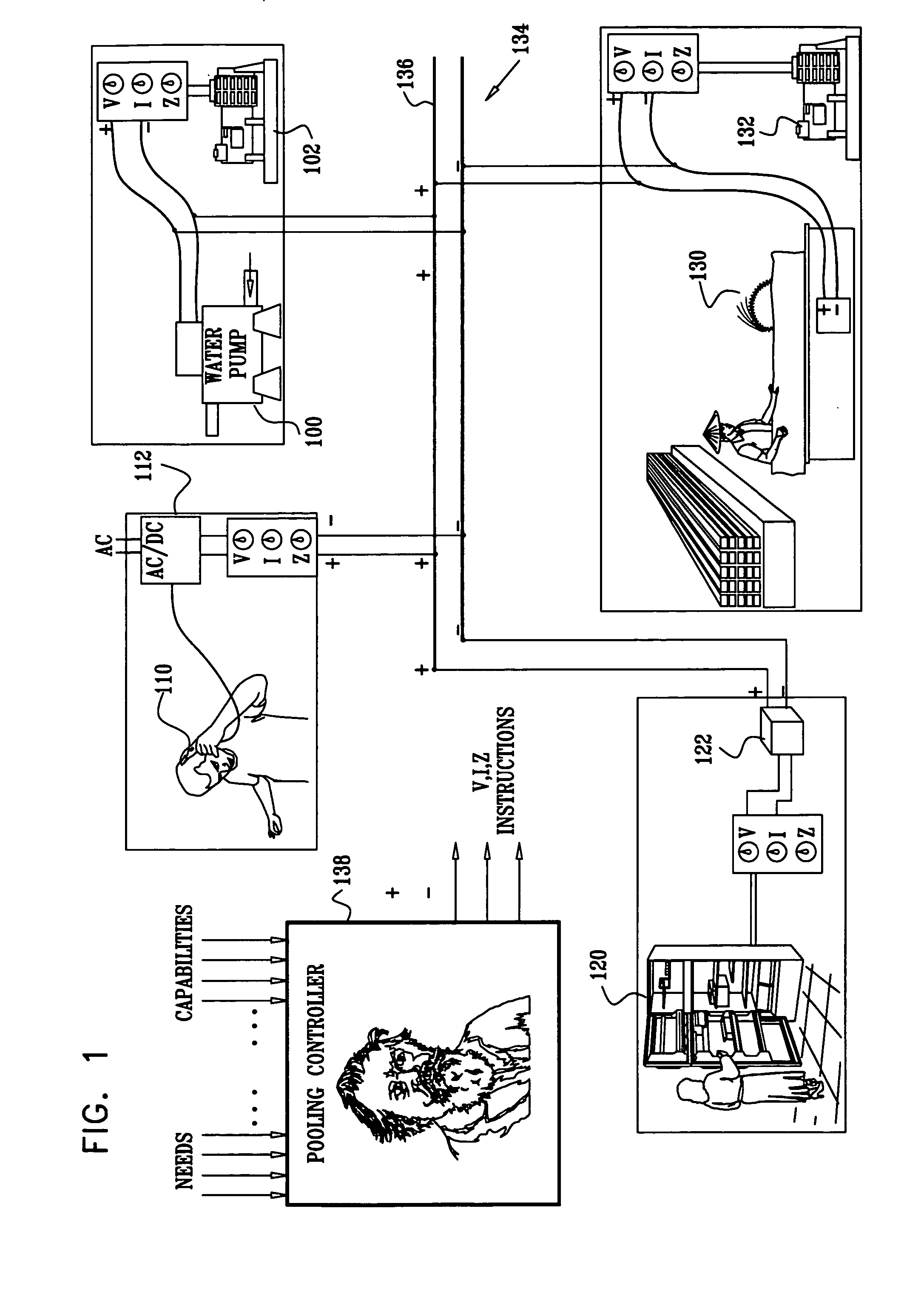
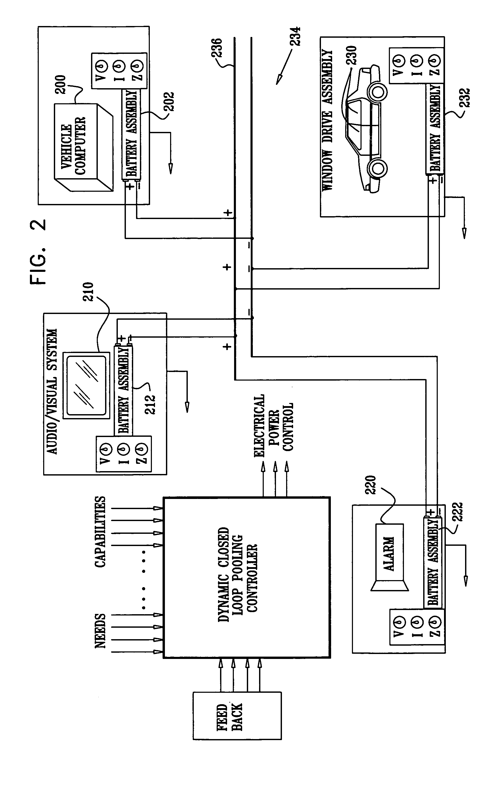
[0163] The present embodiments enable a system of power pooling among and between entities having at least a first mode in which the entity provides more DC electrical power than it consumes and a second mode in which the entity consumes more DC electrical power than it provides, the power pooling system being operative to function under at least one pooling controller.

[0164] Before explaining at least one embodiment of the invention in detail, it is to be understood that the invention is not limited in its application to the details of construction and the arrangement of the components set forth in the following description or illustrated in the drawings. The invention is applicable to other embodiments or of being practiced or carried out in various ways. Also, it is to be understood that the phraseology and terminology employed herein is for the purpose of description and should not be regarded as limiting.

[0165] Reference is now made to FIG. 1, which is a simplified symbolic i...


PUM


Abstract

The present invention provides for a supply interface unit for use in a DC power pooling system, the DC power pooling system comprising a plurality of DC electrical power consuming and providing entities, each of the DC electrical power consuming and providing entities having at least a first operative mode in which it may provide more electrical power than it consumes and a second operative mode in which it may consume more electrical power than it provides, and at least one pooling controller, the supply interface unit comprising: a first port and a second port; a controller; at least one controllable switch, operable by said controller to enable current flow from one of said first port to said second port and said second port to said first port; and at least one current limiter, operable by said controller to limit said current flow.

Description

CROSS-REFERENCE TO RELATED APPLICATIONS [0001] The present application claims priority from PCT Patent Application No. PCT / IL03 / 00832 filed Oct. 14, 2003, which claims priority from U.S. Provisional Patent Application No. 60 / 418,599 filed Oct. 15, 2002, whose entire contents are incorporated herein by reference.BACKGROUND OF THE INVENTION [0002] The present invention relates to the field of powering a system comprising multiple components, and in particular to a system and entities for DC power pooling. [0003] Systems comprising multiple modules, such as communication systems, commonly comprise modules having on-board power supplies that are connected to a common mains. In order to provide uninterrupted operation of the system, including during failure of power mains, systems often comprise a back-up power supply, such as an uninterruptible power supply (UPS), which during a power interrupt functions to supply AC power to each of modules in the system. [0004] The combination of modu...

Claims


Application Information

Patent Timeline
IPC IPC(8): G05D3/12G06F1/26H02J1/00H02J1/10H02J1/14
CPCG06F1/263H02J1/00H02J3/382H02J1/14H02J1/10H02J2300/20H02J3/381
Inventor PINCU, DAVIDATIAS, ILANLEHR, AMIR
Owner NEVERMORE SOLUTIONS
Why Eureka
Try Eureka