Multi-spring pneumatic barrier gate with gate rod capable of rotating by 90 degrees

A spring-pneumatic roadway and brake lever technology, which is applied in roads, roads, buildings, etc., can solve the problems of increasing the operating load of the reducer, failure of the barrier, easy failure, etc., and achieves reduced power requirements, reduced strength requirements, and wind resistance performance Good results

Pending Publication Date: 2022-07-08
朱夕青
View PDF0 Cites 0 Cited by
  • Summary
  • Abstract
  • Description
  • Claims
  • Application Information

AI Technical Summary

Problems solved by technology

When this kind of barrier is installed in a place with a large crossing span, on the one hand, the aluminum barrier is required to be very long, and the strength of the aluminum barrier is high; on the other hand, when the barrier is raised and lowered, the The power and rotational torque of the motor are required to be large, and the aluminum barrier bar is easy to shake, especially when running in windy weather, the noise caused by the shaking of the aluminum barrier bar is large
[0004] In addition, a power outage will cause the barrier gate to fail. When the barrier gate is driven up and down manually, the overturning of the barrier gate will drive the reducer to operate together, increasing the operating load of the reducer, and it is also prone to failure or damage. The operation can only be carried out after opening the chassis of the gate movement, which is very inconvenient to operate

Method used


Image

  • Multi-spring pneumatic barrier gate with gate rod capable of rotating by 90 degrees
  • Multi-spring pneumatic barrier gate with gate rod capable of rotating by 90 degrees
  • Multi-spring pneumatic barrier gate with gate rod capable of rotating by 90 degrees

Examples


Embodiment Construction

[0024] The technical solutions in the embodiments of the present invention will be clearly and completely described below with reference to the accompanying drawings in the embodiments of the present invention. Obviously, the described embodiments are only a part of the embodiments of the present invention, but not all of the embodiments.

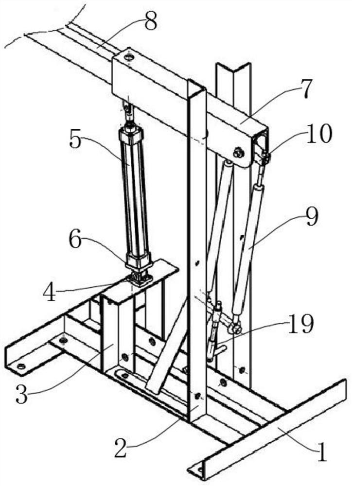
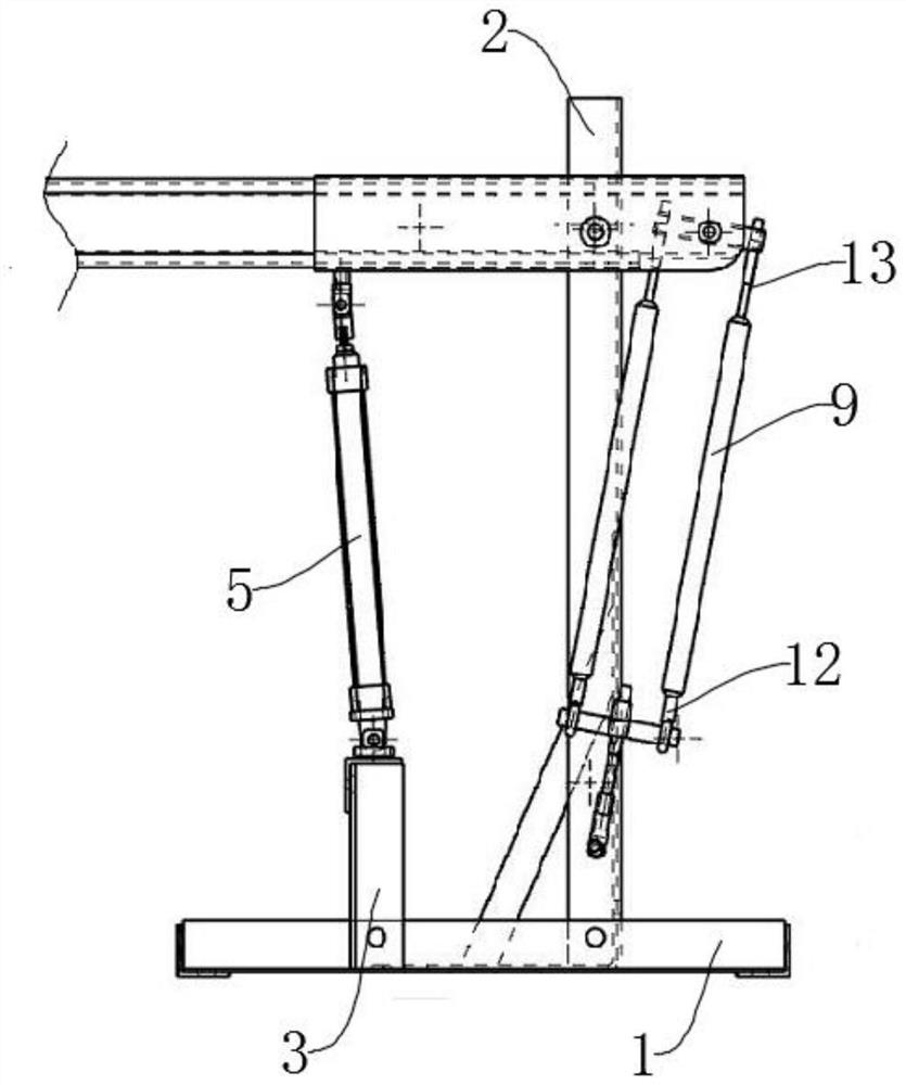
[0025] The present invention provides such as Figure 1-Figure 6 The shown multi-spring pneumatic gate with a gate lever capable of rotating 90 degrees includes an I-shaped bottom plate 1 and two triangular support frames 2 symmetrically installed on its top surface, a fisheye bearing, a fisheye shaft 19, and a screw. Column 18, cross 16, wherein the fisheye bearing is connected with fisheye shaft 19, cross 16, stud 18 respectively;

[0026] Fisheye bearing: the bottom is the fixed end, the top is the movable end, the fixed end and the hole on the vertical plate assembly are connected by thread, and the fisheye bearing is connected with the...


PUM


Abstract

The invention discloses a multi-spring pneumatic barrier gate with a gate bar capable of rotating by 90 degrees, and belongs to the technical field of barrier gate equipment.The multi-spring pneumatic barrier gate comprises an I-shaped bottom plate and two triangular supporting frames symmetrically installed on the top surface of the I-shaped bottom plate, the multi-spring pneumatic barrier gate with the gate bar capable of rotating by 90 degrees is characterized by comprising a fisheye bearing, a fisheye shaft, a stud and a cross, wherein the fisheye bearing is connected with the fisheye shaft, the cross and the stud, the bottom of the fisheye bearing is a fixed end, the top of the fisheye bearing is a movable end, the fixed end is in threaded connection with a hole in the vertical plate assembly, and the fisheye bearing is connected with the fisheye shaft and used for reducing friction. According to the multi-spring pneumatic barrier gate with the gate rod capable of rotating by 90 degrees, noise in the rising and falling process is low through the air cylinder, and the wind resistance of the aluminum barrier gate rod is good through the end face bearing; power can be provided by the air storage tank during power failure; the use of the tension spring reduces the power requirement of the cylinder, and more energy is saved.

Description

technical field [0001] The invention belongs to the technical field of gate equipment, and in particular relates to a multi-spring pneumatic gate with a gate lever capable of rotating 90 degrees. Background technique [0002] The road gate, also known as the car stopper, is a channel entrance and exit management device used to restrict motor vehicles on the road. [0003] At present, the ups and downs of barriers are generally driven by motors. When this kind of gate is installed in the occasion with a large crossing span, on the one hand, the required aluminum gate rod is very long, and the strength of the aluminum gate rod is high; on the other hand, when the gate is lifted and lowered, The power and rotation torque of the motor are required to be large, and the aluminum gate is easy to shake, especially when running in strong winds, the noise caused by the shaking of the aluminum gate is large. [0004] In addition, the power failure will cause the barrier to fail. When...

Claims


Application Information

Patent Timeline
Patent Type & Authority Applications(China)
IPC IPC(8): E01F13/06
CPCE01F13/06
Inventor 熊世豪区伟全余娇朱夕青
Owner 朱夕青
Why Eureka
Try Eureka