
Method of defect control

a defect detection and defect technology, applied in the field of defect detection methods, can solve the problems of reducing the throughput of production lines, affecting the property of integrated circuits more seriously, and small particles and defects are unavoidable, so as to improve the sensitivity of defect detection, reduce the loading of sem review, and shorten the response time

Inactive Publication Date: 2005-04-14
POWERCHIP SEMICON CORP
View PDF8 Cites 5 Cited by
  • Summary
  • Abstract
  • Description
  • Claims
  • Application Information

AI Technical Summary

Benefits of technology

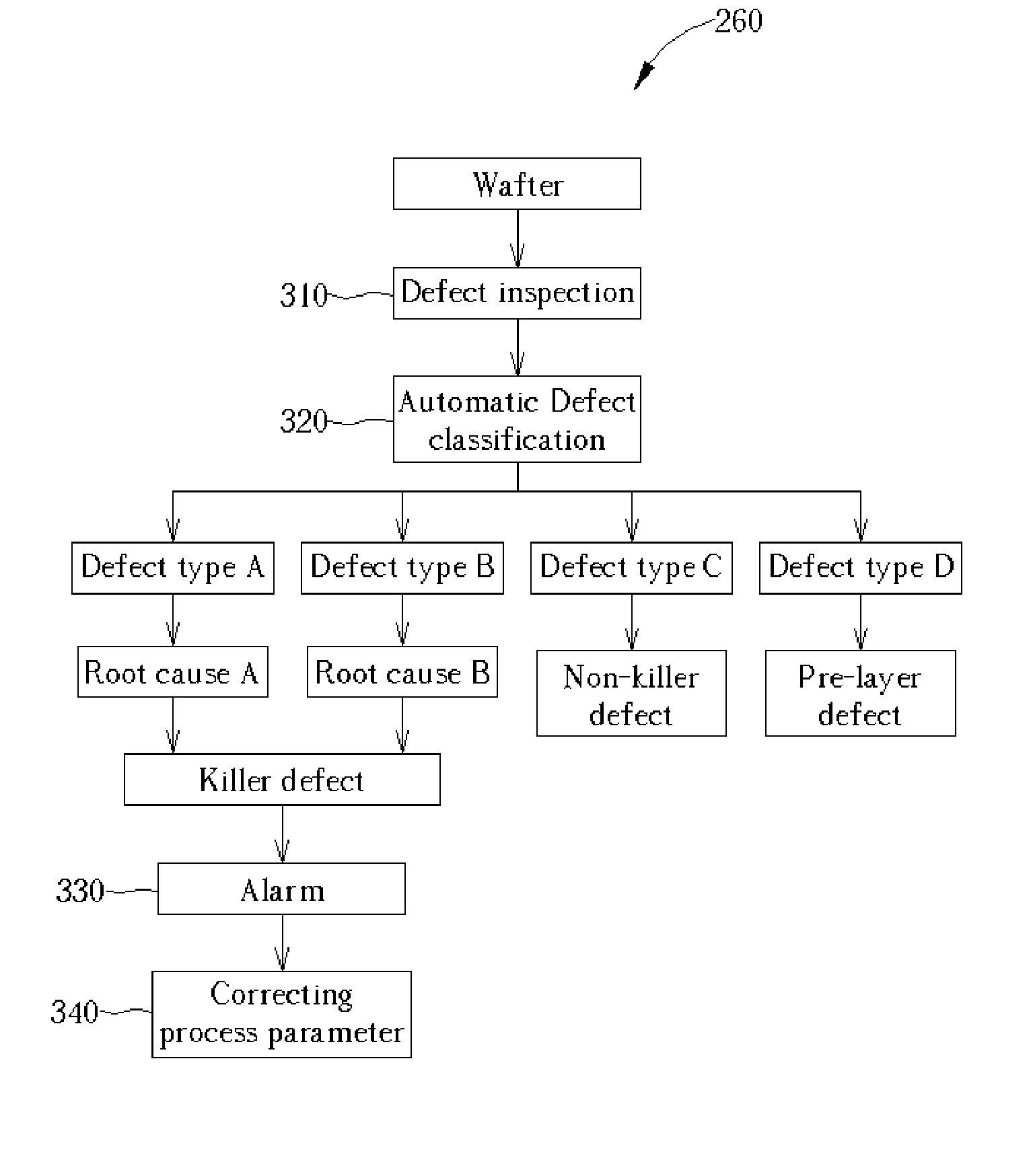
[0010] It is therefore a primary objective of the claimed invention to provide a method of defect control with low cost, fast response and high sensitivity to solve the aforementioned problems in the prior art.
[0012] It is an advantage of the claimed invention that a product wafer can be used for defect detection and an automatic defect classification is carried out by a predetermined database. Thus, the prelayer defects and the adding defect can be separated without a pre-scan process. In addition, by separating killer defects and non-killer defects, it can further reduce the loading of the SEM review, shorten the response time, and improve the sensitivity of the defect detection, thereby improving yield and reliability of products.

Problems solved by technology

In the semiconductor fabricating process, some small particles and defects are unavoidable.
As the size of devices shrinks and the integration of circuits increases gradually, those small particles or defects affect the property of the integrated circuits more seriously.
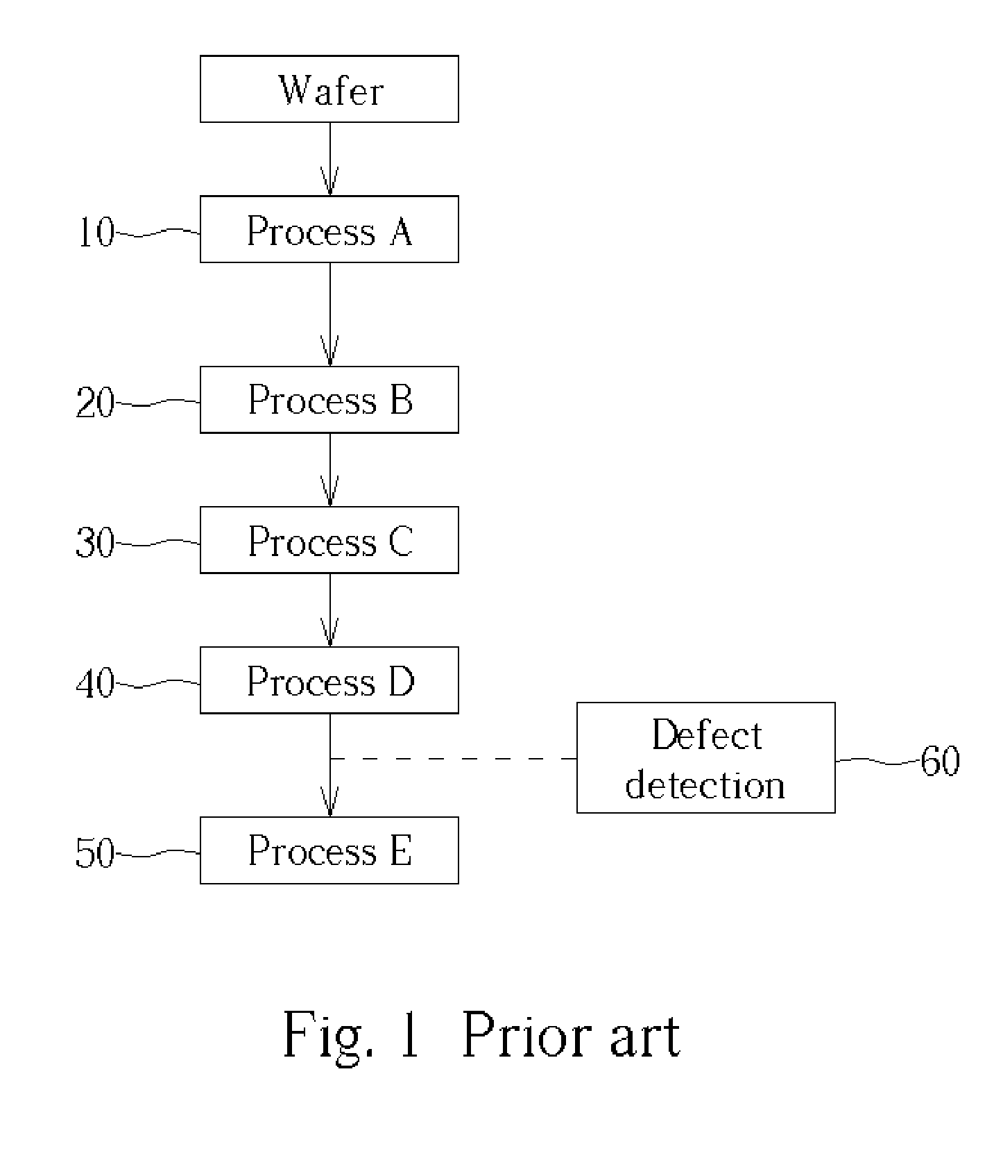
Conventional technology has many disadvantages of using bare wafers to perform a daily check for machines or a sampling examination by grouping for inline products.
For example, the former will waste a lot of bare wafers and reduce the throughput of the production lines, leading to a significant increase in the fabrication cost.
In addition, since only some limited bare wafers are used as a tool monitor, it is hard to find the integrating defects, which are caused by a plurality of processes, in the bare wafer test.
It is also hard to detect the occasional excursion case, which happens easily in mass production.
Though those occasional excursion cases can be detected sometimes indeed, it still cannot provide enough data to perform defect analysis and solve problem of the excursion case.
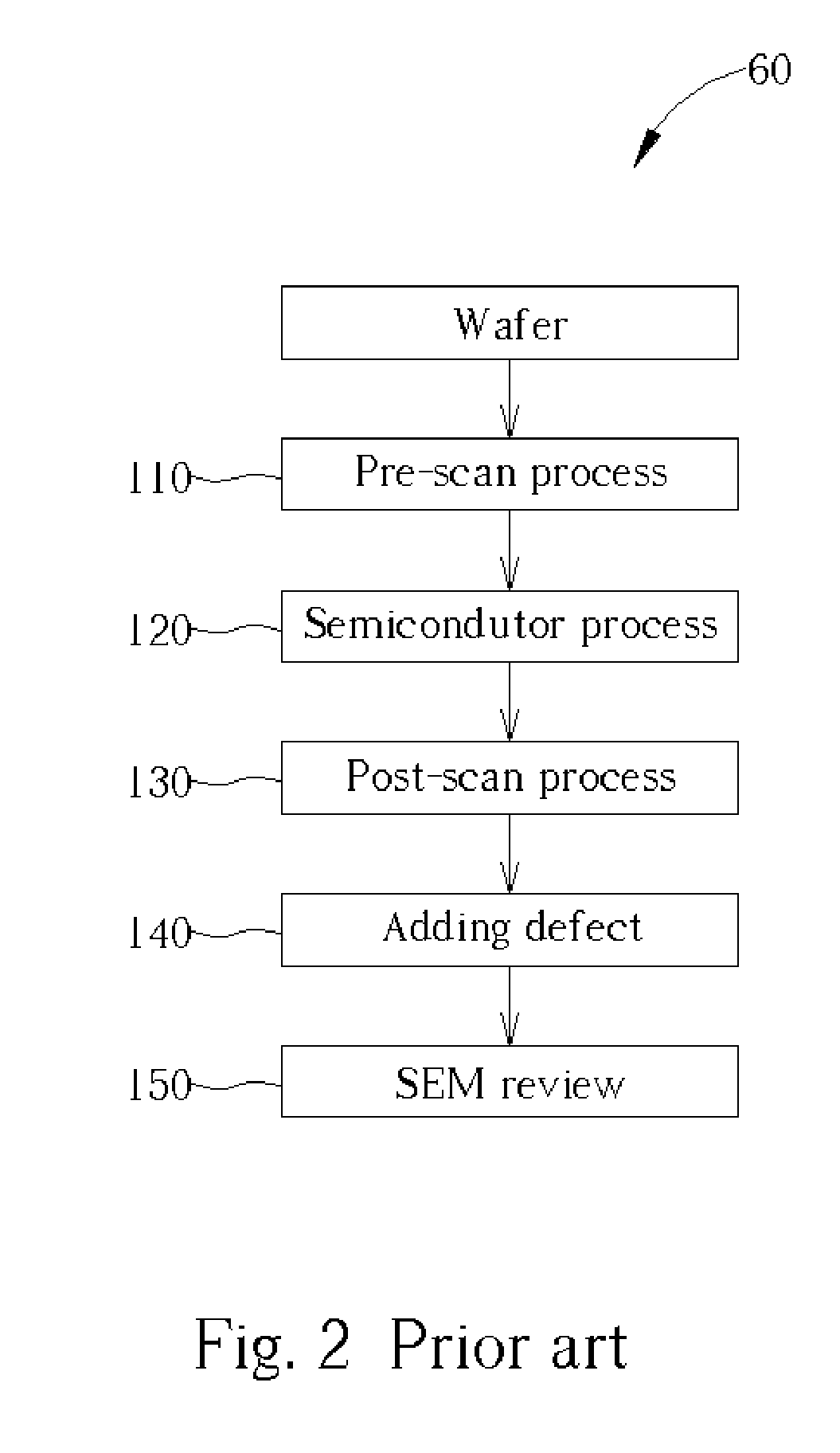
In addition, the conventional defect detection 60 takes a long response time.
However, it is obvious that all the product wafers made in these days may have the same type of defects.
It is a fatal problem in mass production steps, leading to a significant yield loss and high fabrication cost.
Furthermore, as the size of wafers increases from 8 inches to 12 inches, this problem becomes even more serious.

Method used


Image

  • Method of defect control
  • Method of defect control
  • Method of defect control

Examples


Embodiment Construction

[0016] Please refer to FIG. 3 and FIG. 4, which are schematic diagrams of a method of defect control in the present invention. As shown in FIG. 3, in the fabricating procedure, five semiconductor processes, which are process A 210, process B 220, process C 230, process D 240, and process E 250, are performed for a wafer. Each semiconductor process makes a plurality of defects on the wafer. The process B is illustrated in the following to describe the method of defect control of the present invention. First, it is noted that an additional bare wafer is not required in the present invention. The test in the present invention is carried out by using a patterned wafer in the production line as a monitor wafer. In other words, the source of testing is a product wafer instead of a bare wafer, which is used in the prior art. Thus, after some non-destructive tests being carried out, those product wafers used in the tests can be put back into the production line for performing next fabricati...


PUM


Abstract

A method of defect control by daily checking. First, a patterned wafer with a plurality of first defects is provided. After performing a semiconductor process, which generates a plurality of second defects on the wafer, a defect detecting process is performed to detect the first defects and the second defects. Then, the first defects and the second defects are divided according to a predetermined database. The second defects are classified into a plurality of defect types according to the predetermined database.

Description

BACKGROUND OF INVENTION [0001] 1. Field of the Invention [0002] The present invention relates to a method of defect control, and more particularly, to a method of defect control by using a patterned wafer as a monitor wafer in a semiconductor fabricating process. [0003] 2. Description of the Prior Art [0004] In the semiconductor fabricating process, some small particles and defects are unavoidable. As the size of devices shrinks and the integration of circuits increases gradually, those small particles or defects affect the property of the integrated circuits more seriously. For improving the reliability of semiconductor devices, a plurality of tests are performed continuously. According to the test result, process parameters are tuned correspondingly to reduce a presence of defects or particles so as to improve the yield and reliability of the semiconductor fabricating process. [0005] Please refer to FIG. 1, which is a schematic diagram of a conventional semiconductor fabricating p...

Claims


Application Information

Patent Timeline
Patent Type & Authority Applications(United States)
IPC IPC(8): H01L21/66G05B19/418H01L21/02
CPCG05B19/41875G05B2219/32187G05B2219/32222G05B2219/32211G05B2219/32196Y02P90/02Y02P90/80
Inventor LIN, LONG-HUI
Owner POWERCHIP SEMICON CORP
Learn More