
Method & apparatus for retarding fire in a telecommunications box

a technology for telecommunication boxes and fire retardants, applied in the direction of cooling/ventilation/heating modifications, printed circuit board receptacles, support structure mounting, etc., can solve problems such as financial loss, public disarray and dissatisfaction with services, panic,

Inactive Publication Date: 2005-04-14
MAKOOI BABAK B +7
View PDF17 Cites 12 Cited by
  • Summary
  • Abstract
  • Description
  • Claims
  • Application Information

AI Technical Summary

Benefits of technology

[0014] The present invention offers a manner in which to retard a heating or overheating condition and to provide adequate air flow. There is provided a manner in which to maintain a working temperature environment in an electronics device and, furthermore, to prevent a fire in a telecommunications device or at least to reduce the flames of a fire substantially so that the fire can be brought under control or stopped from spreading. More specifically, the invention provides a manner in which to fulfill the inflammability standards in telecommunications devices.
[0019] An object of the present invention is to provide to prevent a fire in a telecommunications device.
[0020] An object of the present invention is to reduce the flames of a fire substantially so that the fire can be brought under control or stopped from spreading.
[0023] In accordance with these and other objects of the invention, there is provided an apparatus for retarding a fire condition of a telecommunications component mounted on a module to be inserted into a telecommunications box, the module having a planar surface having a first side and a second side generally opposed to the first side. A ventilator provides a cross air flow generally in a direction from the first side to the second side. A first opening in the telecommunications box in an area adjacent of the first side of the planar surface forms a substantial portion of the cross air flow emanating from the first side. A second opening in the telecommunications box arranged in an area adjacent to the second side of the planar surface exhausts the cross flow air, such that the cross flow air substantially retards the fire condition.
[0024] A method is provided for retarding a fire condition of a telecommunications component mounted on a planar surface of a module housed in a telecommunications box, the planar surface having a first side and a second side generally opposed to the first side, wherein a ventilator that provides a cross air flow generally in a direction from the first side to the second side. A step of arranging arranges a first opening in the telecommunications box in an area adjacent of the first side of the planar surface in order to form a substantial portion of the cross air flow emanating from the first side. A step of arranging arranges a second opening in the telecommunications box in an area adjacent to the second side of the planar surface in order to exhaust the cross flow air, such that the cross flow air substantially retards the fire condition.

Problems solved by technology

In the case of a fire, telecommunication could be lost over vast geographic areas, which could result in financial loss, public disarray and dissatisfaction with services, and even panic.
As will be explained, this philosophy is problematic.
Another problem that frustrates the standardized testing is that different telecommunications boxes are differently configured.
Moreover, the heating dissipation characteristics change in a way that is unexpected.
However, the heat dissipation problems are exacerbated in the case of a module removed, particularly for those adjacent the module experiencing a fire.
This is because, without the physical profile of the module, there is inadequate air resistance adjacent the missing module.
As a result, an adequate air flow cannot be ensured and, thus, adequate cooling cannot be maintained.
This is certainly problematic, because certain customer configurations do not require functional optical networking circuit packs.
The critical components receive less cooling and can overheat causing reduced system life or in some cases system failure.

Method used


Image

  • Method & apparatus for retarding fire in a telecommunications box
  • Method & apparatus for retarding fire in a telecommunications box
  • Method & apparatus for retarding fire in a telecommunications box

Examples


Embodiment Construction

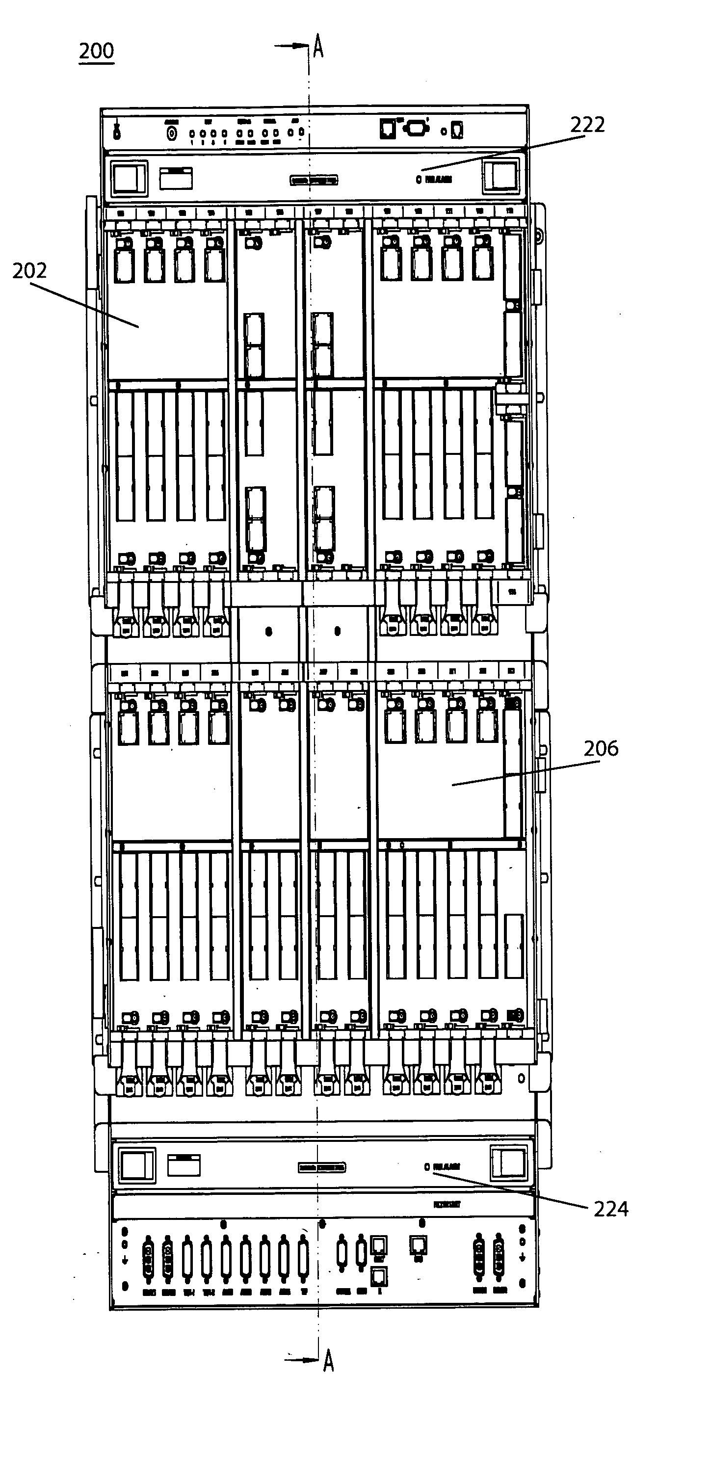
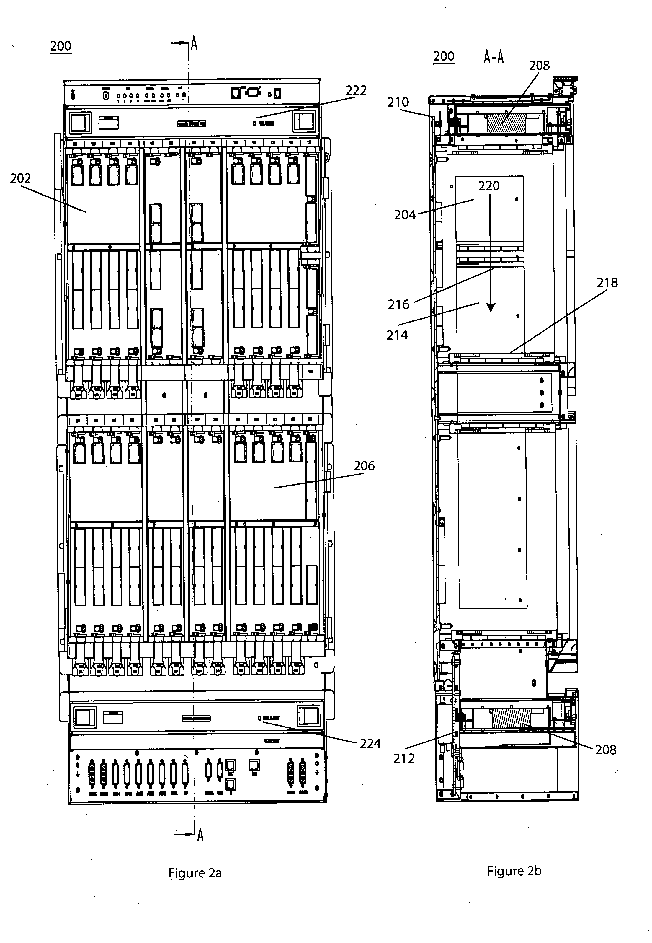
[0028] The invention will now be discussed in reference to FIGS. 2a and 2b wherein front and side-cross section views, respectively, a telecommunications box 200 are generally shown. Modules 202 with telecommunication components 204 mounted thereon are inserted, in this case vertically, into the box 200. The box may contain frames, generally shown by reference numeral 206.

[0029] One or more ventilators 208, which may be arranged singularly in several next to each other in a module. In one aspect of the invention, the inventive aspect is to control the ventilator 208 or ventilators in dependence on an air pressure created by the temperature within the box 200.

[0030] In one aspect of the invention, the ventilator turns dependent on the measured ambient temperature at a predetermined temperature resistance. This creates the general air flow which tends to cool the electronic components of the telecommunications device. Due to the control of the ventilators in this manner, another adv...


PUM


Abstract

Retarding a fire condition of a telecommunications component mounted on a module to be inserted into a telecommunications box is provided. The module may have a planar surface having a first side and a second side generally opposed to the first side. A ventilator provides a cross air flow generally in a direction from the first side to the second side. A first opening in the telecommunications box in an area adjacent of the first side of the planar surface forms a substantial portion of the cross air flow emanating from the first side. A second opening in the telecommunications box arranged in an area adjacent to the second side of the planar surface exhausts the cross flow air, such that the cross flow air sub-stantially retards the fire condition. An air flow guide is provided to simulate an air resistance of a module.

Description

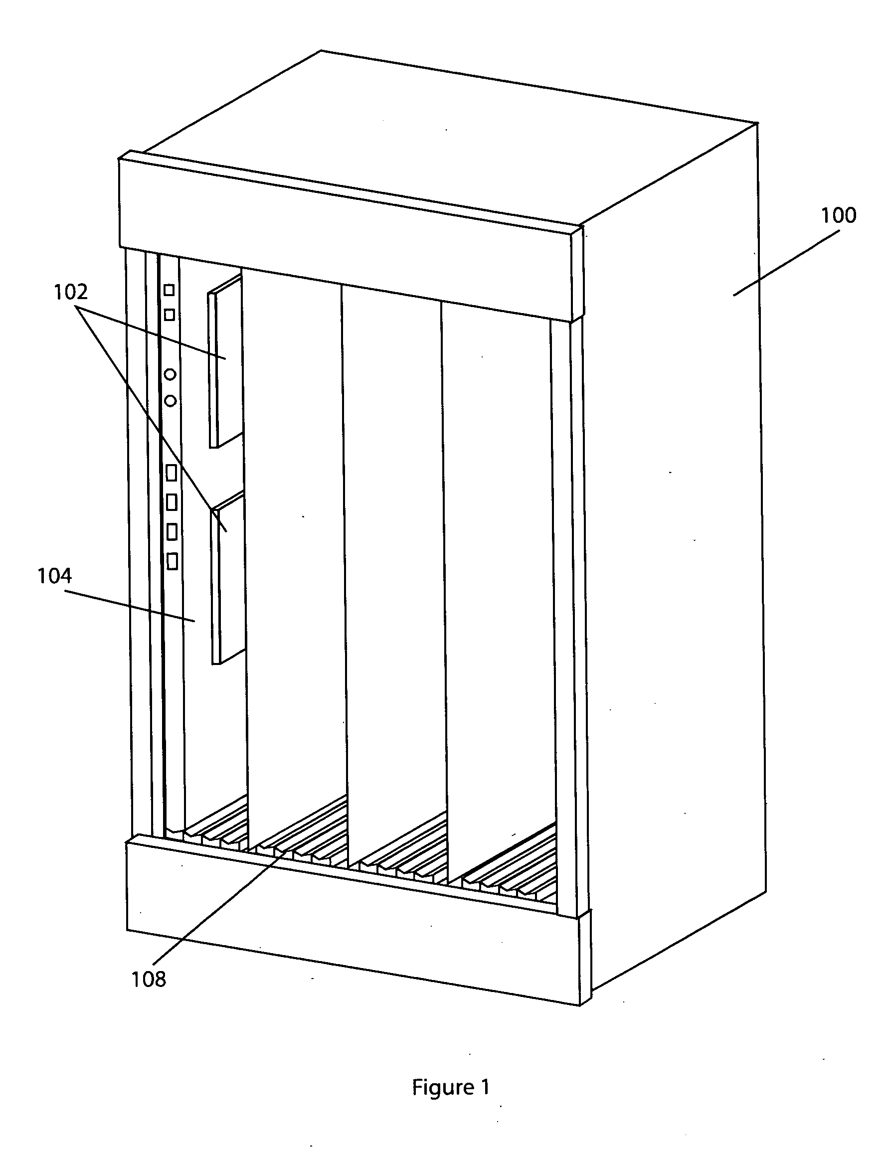
CROSS REFERENCE TO RELATED APPLICATIONS [0001] This application claims priority to the U.S. Provisional application No. 60 / 505698, filed Sep. 24, 2003 and which is incorporated by reference herein in its entirety.FIELD OF INVENTION [0002] The invention relates to retard a heating or over-heating condition and to provide adequate air flow and, more particularly, to meet the inflammability standards in telecommunications devices. BACKGROUND OF INVENTION [0003] Telecommunications devices must adhere to certain standards concerning fire security and inflammability. Compliance with these standards is terribly important particularly for public communications. In the case of a fire, telecommunication could be lost over vast geographic areas, which could result in financial loss, public disarray and dissatisfaction with services, and even panic. Therefore, these standards are taken seriously by the industry and all attempts to meet the criteria are taken. [0004] Within a frame 100 of teleco...

Claims


Application Information

Patent Timeline
Patent Type & Authority Applications(United States)
IPC IPC(8): H04Q1/02H04Q1/14H05K7/14H05K7/20
CPCH04Q2201/06H04Q1/035H05K7/20563H05K7/1425
Inventor MAKOOI, BABAK B.GUZIK, GEORGE ANDREWCOLE, GUY A.CROONE, ARTHUR JAMESEDWARDS, EARLHARLAN, DON D.POLACEK-ATTENBERGER, CHRISTIANSCHUSTER, SIEGWALD
Owner MAKOOI BABAK B
Learn More