
Device to Extinguish a Fire Produced in a Building

a technology for extinguishing fires and buildings, applied in fire rescue, ammunition projectiles, weapons components, etc., can solve the problems of general collapse of buildings, furniture and files are destroyed, and it is difficult to extinguish fires, so as to achieve the effect of safe hitting the corresponding areas of buildings and easy smothering fires

Inactive Publication Date: 2008-05-22
HERNANDEZ REINA JOSE ANTONIO
View PDF9 Cites 4 Cited by
  • Summary
  • Abstract
  • Description
  • Claims
  • Application Information

AI Technical Summary

Benefits of technology

[0014]With the invented device, it is possible to immediately extinguish or considerably reduce the flames of a building on fire.
[0015]These bombs, when they are missile-shaped, may also be launched from a distance to enable firemen to act at a much greater safety distance.
[0016]Besides, with this device, floors of the building that are inaccessible to water hoses on being too high, may be reached.
[0017]In short, with the invented device, whether the bomb is spheroid or missile-shaped, it may be launched either from a helicopter or with a gun from a distance and conveniently and safely hit the corresponding areas of the building and thus easily smother the fire that the building is suffering.
[0018]The guns may be installed in ground vehicles to accurately launch the bombs and hit the affected zone or zones of the building.
[0019]These guns, when they are small in size, may be carried by people and used to launch the bombs with the corresponding fire-retarding product.

Problems solved by technology

At present, there are important problems at the time of extinguishing a fire in a building, especially if it is of considerable height, since technical means are unable to smother flames at a certain height.
In this way, for example, water pressure is insufficient to reach a specific height, facilitating the spread of flames to heights above, turning out to be practically impossible to extinguish the fire, and its structure, generally steel, suffers sufficiently to cause the general collapse of the building.
It is well-known that when this circumstance takes place, furniture and files are destroyed, only the skeleton or structure of the building remaining at the mercy of the flames.
The problems that this type of fires produce are not only material, but, in general, are accompanied by human losses.

Method used


Image

  • Device to Extinguish a Fire Produced in a Building
  • Device to Extinguish a Fire Produced in a Building

Examples


Embodiment Construction

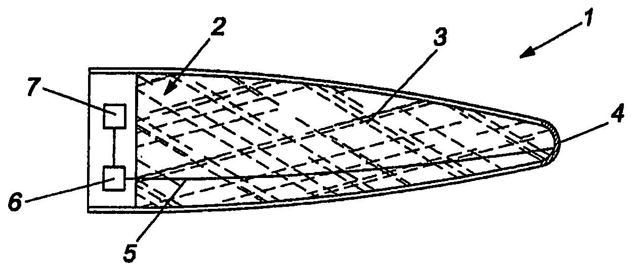
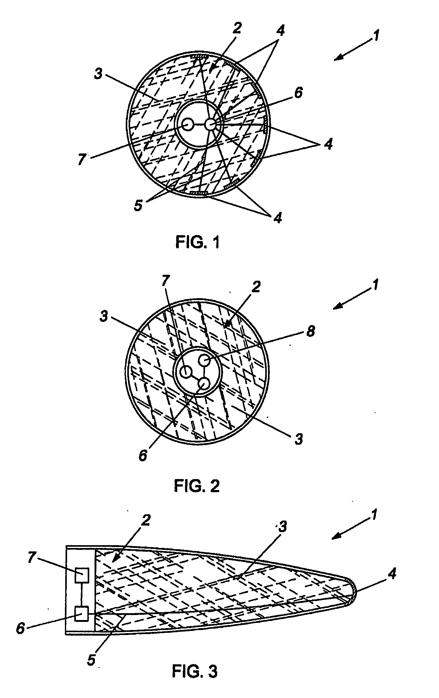
[0007]The invented device comprises a preferably spheroid-shaped body, enclosed within which is a space containing an explosive charge with a detonator, which causes the above-mentioned charge, connected by means of electrical wires to an actuator, to explode.

[0008]The actuators are distributed around the surface of the spheroid body, so that, on any of the actuators hitting a part of the building, the explosion of the body, that constitutes a bomb, is produced.

[0009]The fireproof material used to extinguish the fire is contained inside the body.

[0010]As soon as the spheroid-shaped body strikes the building, the explosion is produced and its disintegration or breakup causes fire-retarding material contained within to fall in the area, smothering the flames.

[0011]Among others, this fire-retarding material may be carbon dioxide.

[0012]A variation in the embodiment of the invention is when the body has a missile shape, with a timer at the corresponding end of its nosecone or remote cont...


PUM


Abstract

Device to extinguish a fire produced in a building, characterized by having a bomb comprising a hollow body whose inner part carries a load of a fire-retarding component and an actuator that, when it hits the surface of the building, activates a detonator that makes the charge explode, scattering the fire-retarding component over the whole surface area of the radius of action, the detonator and explosive charge contained inside a receptacle and the detonator being connected by means of an electrical wire to one or various actuators installed on the surface of the body of the bomb.

Description

OBJECT OF THE INVENTION[0001]The present invention refers to a device to extinguish a fire produced in a building.BACKGROUND OF THE INVENTION[0002]At present, there are important problems at the time of extinguishing a fire in a building, especially if it is of considerable height, since technical means are unable to smother flames at a certain height.[0003]In this way, for example, water pressure is insufficient to reach a specific height, facilitating the spread of flames to heights above, turning out to be practically impossible to extinguish the fire, and its structure, generally steel, suffers sufficiently to cause the general collapse of the building.[0004]It is well-known that when this circumstance takes place, furniture and files are destroyed, only the skeleton or structure of the building remaining at the mercy of the flames.[0005]The problems that this type of fires produce are not only material, but, in general, are accompanied by human losses.[0006]To solve these probl...

Claims


Application Information

Patent Timeline
IPC IPC(8): A62C13/00A62C19/00
CPCA62C3/025A62C3/00A62C19/00
Inventor HERNANDEZ REINA, JOSE ANTONIO
Owner HERNANDEZ REINA JOSE ANTONIO
Learn More