
Device for improving the visibility conditions in a motor vehicle

a technology for improving the visibility conditions of motor vehicles and vehicles, which is applied in the direction of reradiation, television systems, instruments, etc., can solve the problems of insufficient selection of vehicle velocity, and achieve the effect of reducing the operating capacity of the device, reducing the consumption of energy, and efficient and reliable operation of the devi

Active Publication Date: 2005-04-07
CHEMTRON RES
View PDF4 Cites 20 Cited by
  • Summary
  • Abstract
  • Description
  • Claims
  • Application Information

AI Technical Summary

Benefits of technology

[0006] The invention is based on the object of specifying a device for improving the visibility conditions in a motor vehicle which reduces these disadvantages and as a result improves traffic safety.

Problems solved by technology

This ensures that the vehicle driver cannot rely on the subjective impression of a particularly good, overestimated visibility owing to the device, and accordingly making an inappropriately high selection of his vehicle velocity V in accordance with his misinterpreted field of vision.

Method used


Image

  • Device for improving the visibility conditions in a motor vehicle
  • Device for improving the visibility conditions in a motor vehicle

Examples


Embodiment Construction

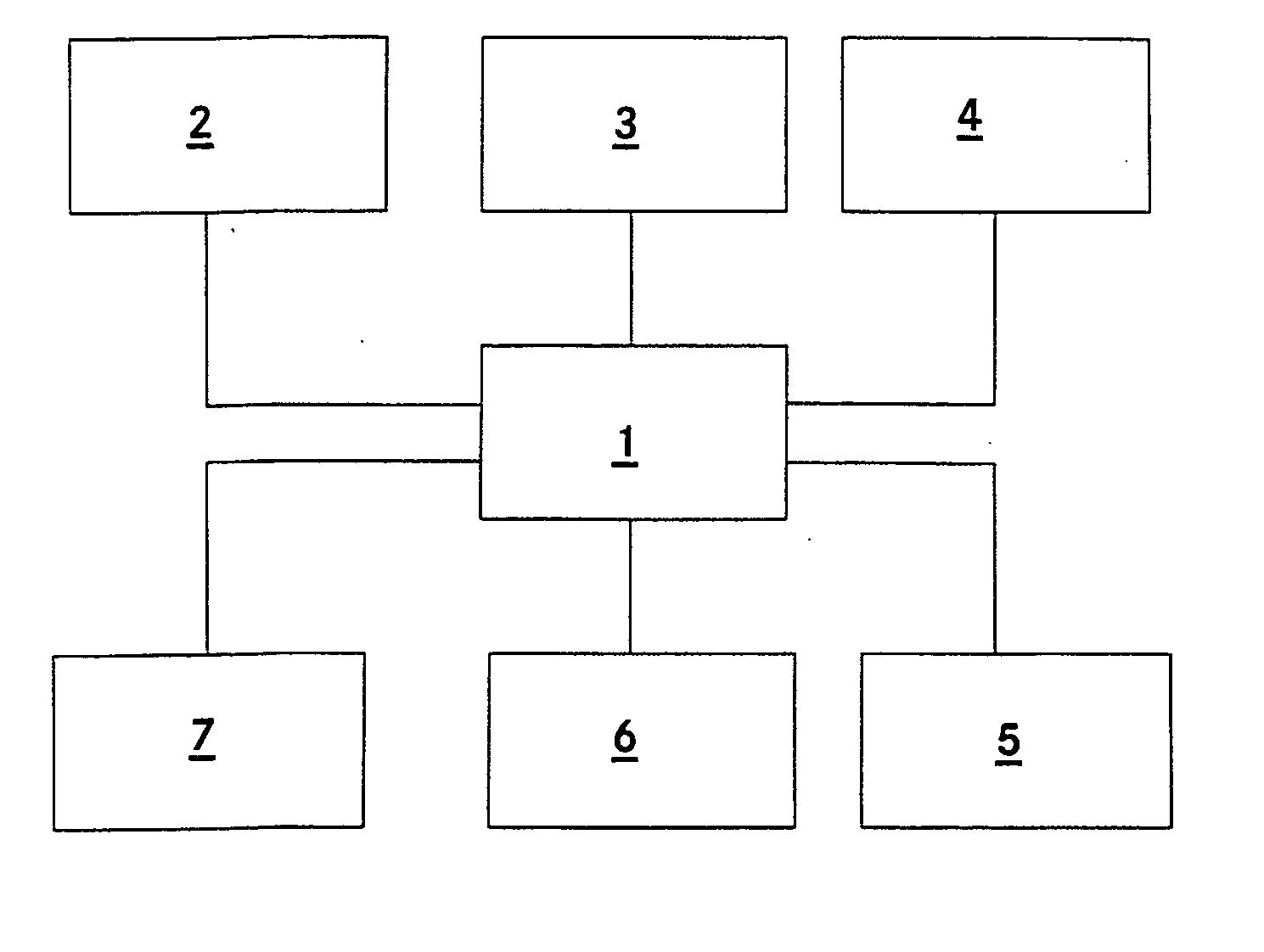
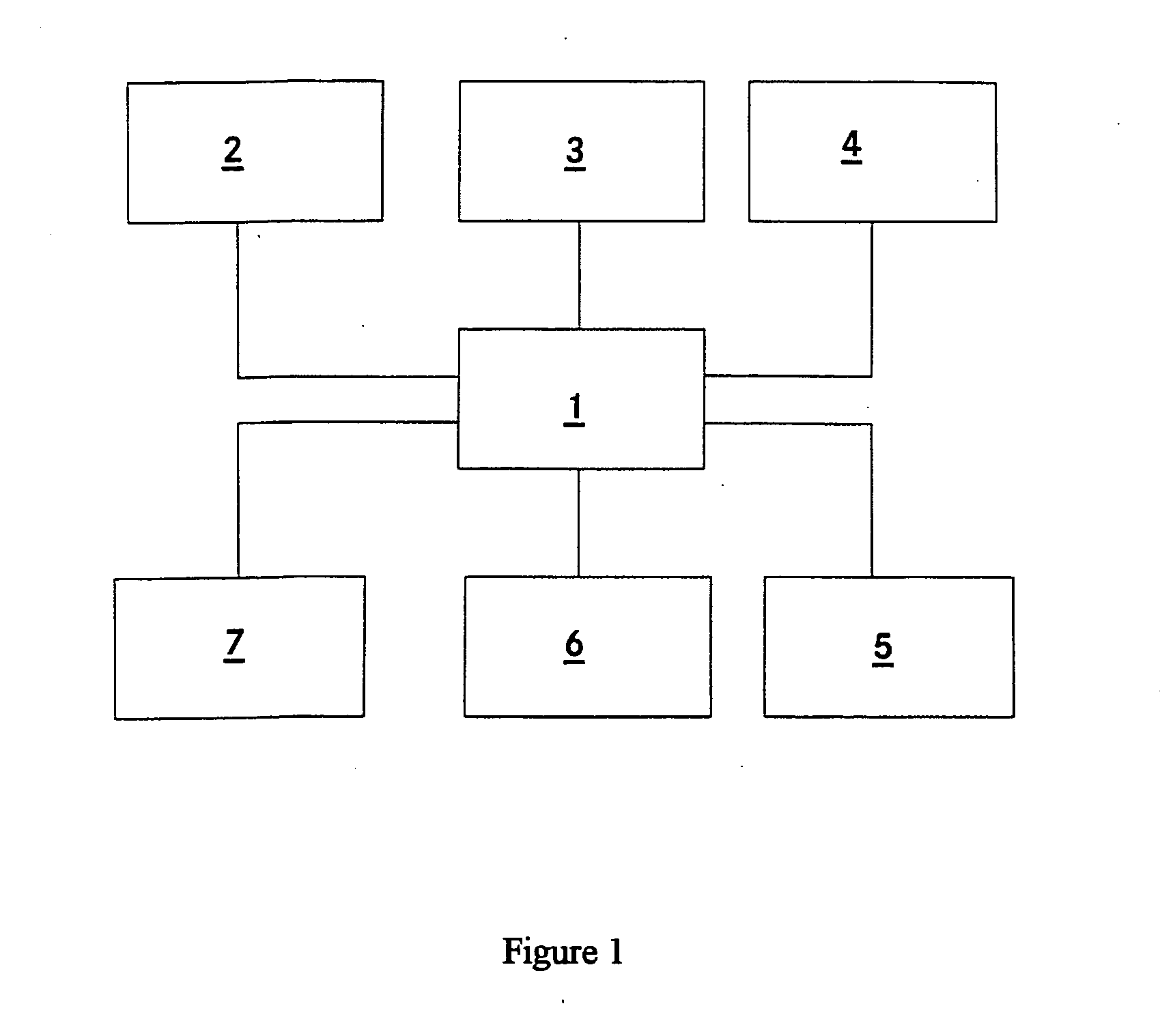
[0031] This device exhibits a radiation source 2 for infrared radiation which irradiates infrared radiation with a wavelength of approximately 800 nm. The radiation source 2 is implemented as an infrared laser. This radiation source 2 is arranged in the front vicinity of the vehicle in the vicinity of the headlights and irradiates the vicinity in front of the vehicle. In addition, this device has an infrared-sensitive camera 3 which is arranged in the vehicle and is orientated in such a way that it senses at least part of the surroundings which are irradiated by the infrared radiation source 2, and feeds the sensed image data to the display 4 via the control unit 1. By means of the display 4, the image data which is fed to it and sensed by the camera 3 is displayed and thus made available to a driver of a vehicle. The control unit 1 controls the infrared radiation source 2, the camera 3 and the display 4 in this context.

[0032] The infrared radiation source 2 radiates infrared radia...


PUM


Abstract

The invention relates to a device for improving the visibility conditions in a motor vehicle, having a radiation source for infrared radiation for irradiating the surroundings of the vehicle, having an infrared-sensitive camera for taking images of at least part of the irradiated surroundings, having a display unit for displaying collected image data, and having a control unit for controlling the device. Furthermore, a sensing unit for a recommended maximum velocity vmax is provided and is connected to the control unit. A velocity sensor which is connected to the control unit is provided in such a way that the control unit causes the display to be switched off when the vehicle velocity v exceeds the maximum velocity vmax. The display is preferably switched on when the vehicle velocity v drops below the maximum velocity vmax. The sensing unit for a recommended maximum velocity vmax is preferably designed in such a way that the recommended maximum velocity vmax is determined from the road profile or from the driving behavior of the vehicle or from received radio signals. This device ensures that the vehicle with the device operates in a safe way for the user.

Description

BACKGROUND OF THE INVENTION [0001] 1. Field of Invention [0002] The invention relates to a device for improving the visibility in a motor vehicle. [0003] 2. Related Art of the Invention [0004] DE 40 32 927 C2 discloses a device for improving the visibility in a motor vehicle having a radiation source for infrared radiation for irradiating the surroundings of the vehicle, and having an infrared-sensitive camera which takes images of the irradiated field of vision of the driver and makes available the collected image data to the driver by means of a display device which is embodied as a head-up display and in which the image data is visually superimposed as a virtual image on the external landscape. By means of this device, the driver can see considerably better at night or under bad weather conditions, in particular when he is dazzled by oncoming vehicles. As a result of the use of infrared radiation, the driver is, in contrast, not dazzled by the oncoming traffic. Such devices of th...

Claims


Application Information

Patent Timeline
Patent Type & Authority Applications(United States)
IPC IPC(8): B60R16/027B60R1/00G08G1/16H04N7/18
CPCB60K2350/2013B60R1/00B60R2300/103H04N7/183B60R2300/302B60R2300/404B60R2300/8053B60R2300/106B60K2360/21B60R1/30B60R1/24
Inventor MOISEL, JOERGHOLZ, MICHAEL
Owner CHEMTRON RES
Learn More