
System and method for local deformable motion analysis

a deformation and motion analysis technology, applied in image analysis, image enhancement, instruments, etc., can solve the problems of difficult tracking of objects, misdiagnosis, and inability to obtain true cardiac motion withou

Active Publication Date: 2005-04-07
SIEMENS MEDICAL SOLUTIONS USA INC
View PDF2 Cites 51 Cited by
  • Summary
  • Abstract
  • Description
  • Claims
  • Application Information

AI Technical Summary

Benefits of technology

The present invention is about a system and method for analyzing local deformable motion in images. The system can identify object image regions and background image regions, and estimate the global motion in an image frame by measuring the motion of multiple background image regions. The global motion is then compensated to measure the local motion of the object. The system can also track the motion of control points or identify static and dynamic regions in an image and fit a parametric shape model to them. The technical effects of the invention include improved accuracy in analyzing local motion in images and improved efficiency in identifying and tracking objects in images.

Problems solved by technology

One issue that commonly arises in tracking the motion of an object is distinguishing the movement of an object from a moving background.
This makes it difficult to track the object, for example, a facial feature.
One of the difficulties in tracking myocardial wall function is to compensate for additional motion introduced by breathing, movement of the body or the ultrasound probe.
However, true cardiac motion cannot be obtained without compensating the external motion.
If no compensation is made for global motion, misdiagnosis can occur.
The principal axis is not widely used for global motion compensation because it does not adequately identify an ischemic region of a heart or similar analysis.
The problem with this method in identifying the abnormal region lies with the original assumption that was made.

Method used


Image

  • System and method for local deformable motion analysis
  • System and method for local deformable motion analysis
  • System and method for local deformable motion analysis

Examples


Embodiment Construction

The present invention is directed to a method for tracking local deformable motion of an object. An example where such a method would be utilized is for tracking the local motion of a myocardial wall to detect regional wall motion abnormalities in the heart. The method may also be used to track the endocardial wall or epicardial wall of the heart. It is to be understood by those skilled in the art that the present invention may be used in other applications where motion tracking is useful such as, but not limited to, recognizing movement of human features such as head movements, facial features, hand movements or other body movements. The present invention can also be used in 2 dimensional, 3 dimensional and 4 dimensional (3D+time) medical analyses of anatomical structures such as the heart, lungs or tumors that are evolving over time.

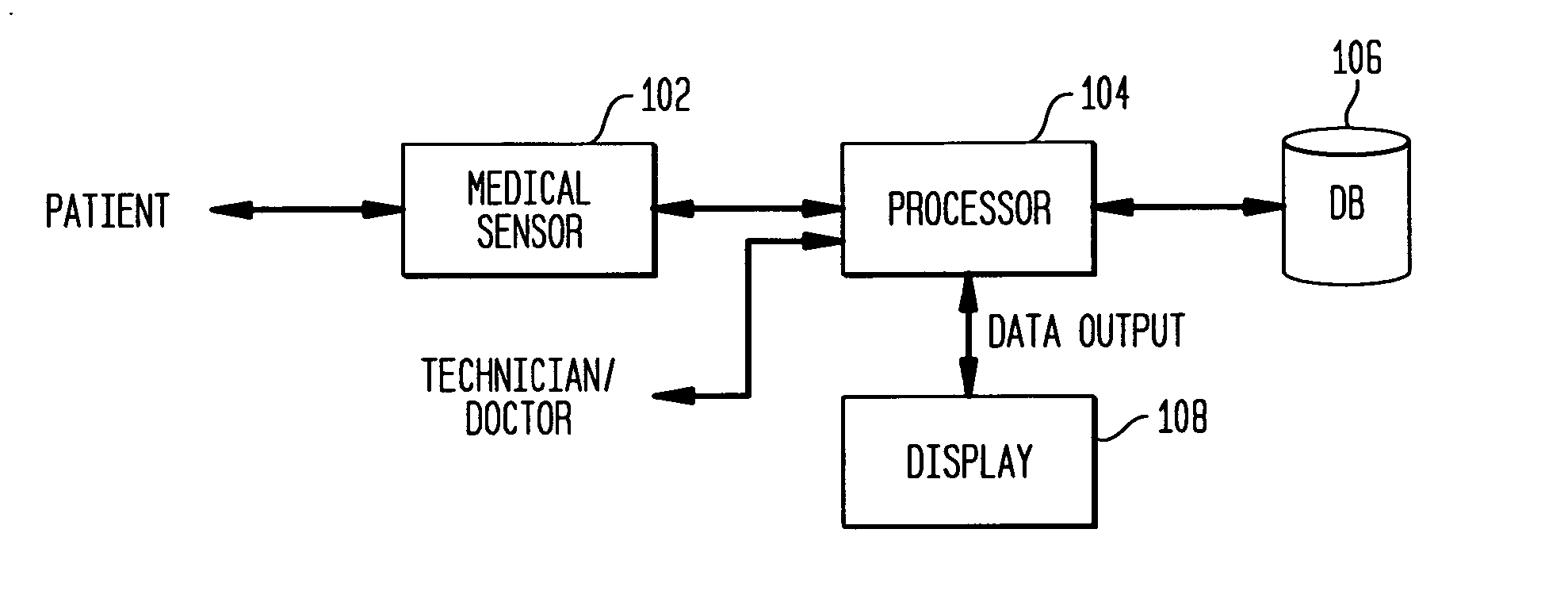
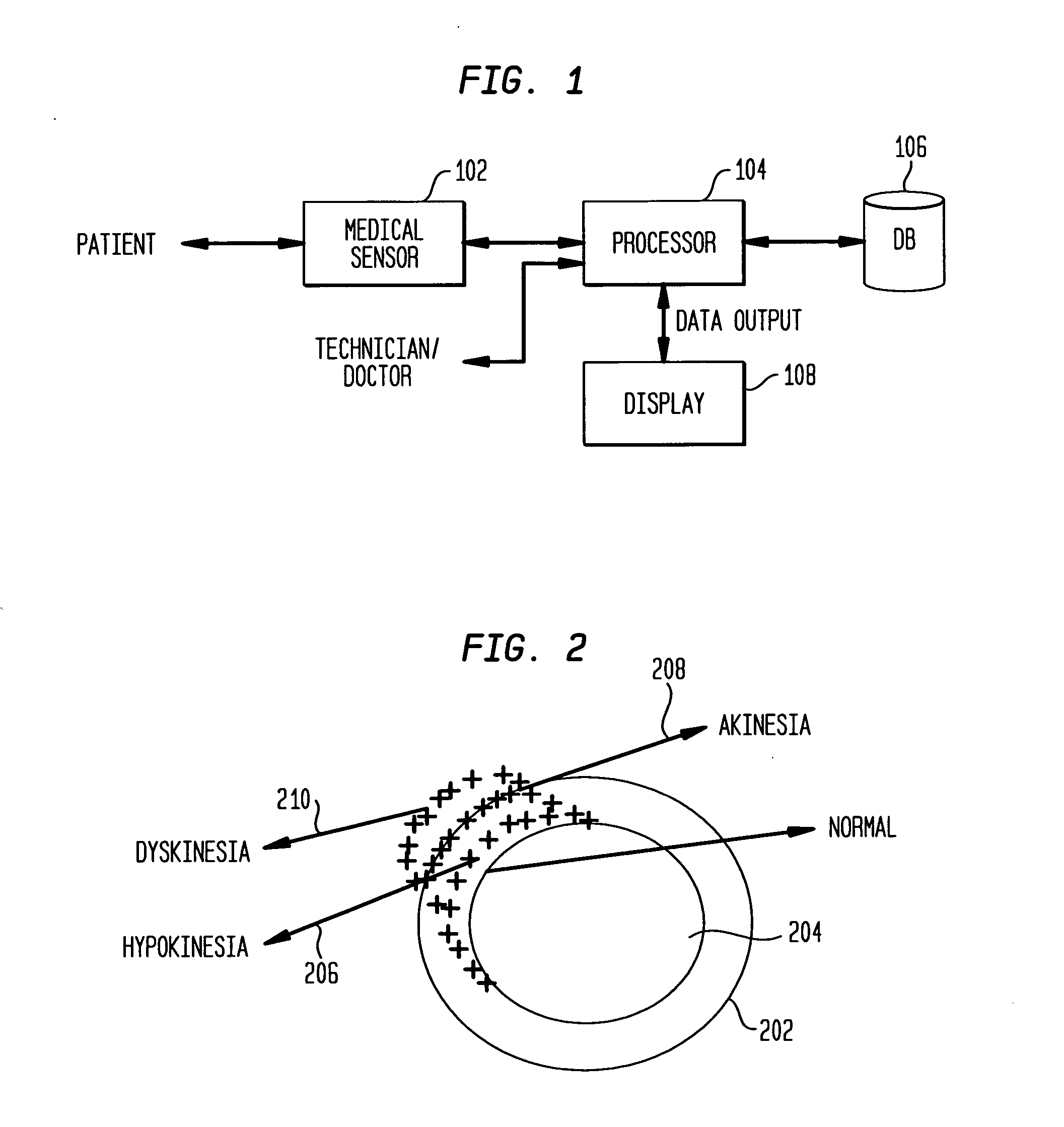
For purposes of describing the present invention, an example will be described for tracking the endocardial wall of the left ventricle. FIG. 1 illu...


PUM


Abstract

A system and method for local deformable motion analysis and for accurately tracking motion of an object isolating local motion of an object from global motion of an object is disclosed. The object is viewed in an image sequence and image regions are sampled to identify object image regions and background image regions. The motion of at least one of the identified background image regions is estimated to identify those background image regions affected by global motion. Motion from multiple background image regions are combined to measure the global motion in that image frame. The measured global motion in the object image regions are compensated to measure local motion of the object and the local motion of the object is tracked. A system and method for accurately measuring the local deformable motion of an object as the relative motion between two control point sets is disclosed. The point sets are defined as the inner contour and the outer contour of an object. The motion of the control point sets is estimated and the relative motion is used to characterize the local deformation and local motion of the object.

Description

FIELD OF THE INVENTION The present invention is directed to a system and method for local deformable motion analysis, and more particularly, to a system and method for accurately tracking motion of an object isolating local motion of an object from global motion of an object. BACKGROUND OF THE INVENTION Object tracking in an important tool used in many imaging software applications. One issue that commonly arises in tracking the motion of an object is distinguishing the movement of an object from a moving background. An example of a scenario is recognizing movement of human features such as head movements, facial features, hand movements or other body movements. In imaging the target image, it becomes clear that the background scenery is also moving in the image (e.g., trees, vehicles, and people). This makes it difficult to track the object, for example, a facial feature. The imaging software must be able to adequately distinguish between the target (i.e., the particular facial f...

Claims


Application Information

Patent Timeline
Patent Type & Authority Applications(United States)
IPC IPC(8): G06K9/00G06T7/20
CPCG06T7/20G06T2207/30048G06T2207/10132G06T7/2046G06T7/0016G06T7/251
Inventor GEORGESCU, BOGDANZHOU, XIANG SEANCOMANICIU, DORINKRISHNAN, SRIRAM
Owner SIEMENS MEDICAL SOLUTIONS USA INC
Learn More