
Electronic component mounting apparatus and electronic component mounting method

a technology for mounting apparatuses and electronic components, applied in the direction of instruments, television systems, manufacturing tools, etc., can solve the problems of wasting real components, not many cases where component recognition processing is properly performed in practice, and many loads

Inactive Publication Date: 2005-04-07
HITACHI HIGH TECH INSTR CO LTD
View PDF4 Cites 18 Cited by
  • Summary
  • Abstract
  • Description
  • Claims
  • Application Information

AI Technical Summary

Benefits of technology

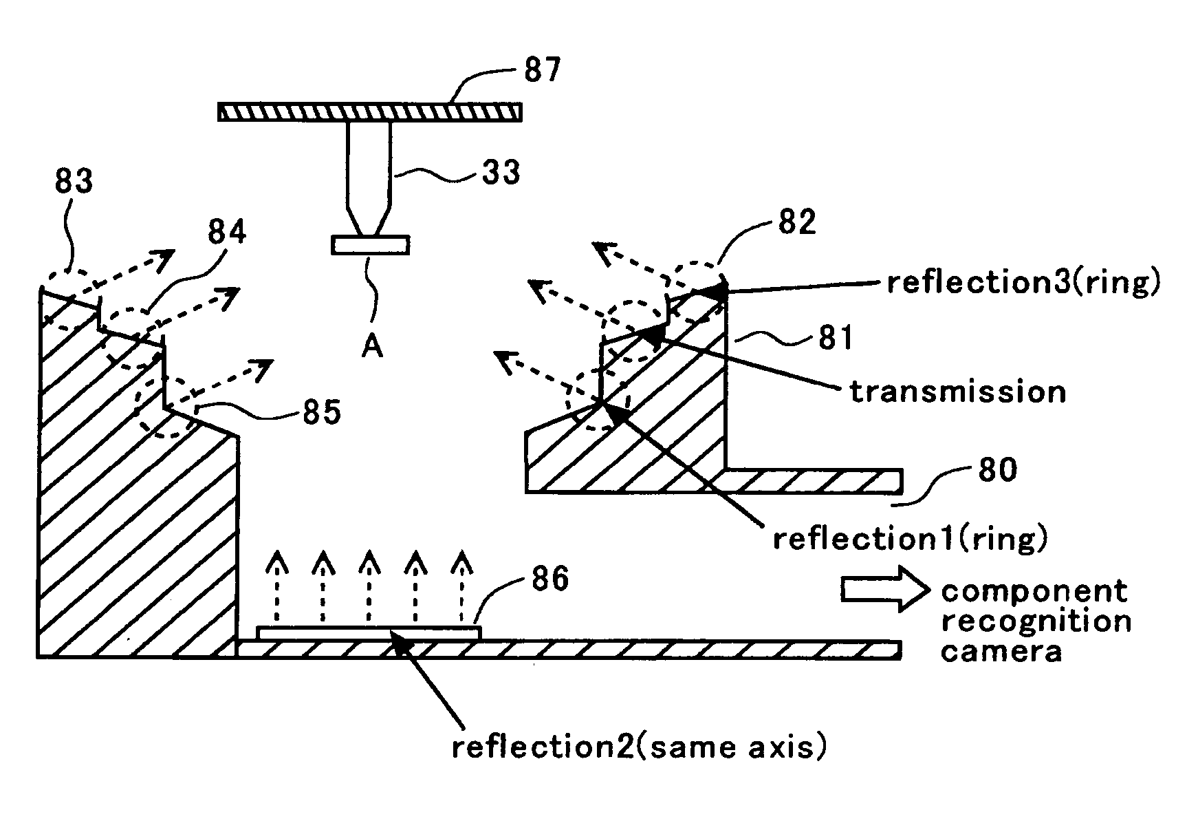
[0009] The invention provides an electronic component mounting apparatus mounting electronic components on a printed board. The apparatus includes a plurality of component feeding units feeding the electronic components, a suction nozzle picking up one of the electronic components from the component feeding units, an illumination device illuminating the electronic component picked up by the suction nozzle, a component recognition camera taking an image of the illuminated electronic component, a recognition processing device performing a recognition processing of the image of the electronic component taken by the component recognition camera, and an image display device. The apparatus also includes a control device which requires the display to display the image of the electronic component taken by the component recognition camera wh

Problems solved by technology

Generally, even when component library data having feature data of electronic components and so on are carefully formed, there are not many cases where component recognition processing is properly performed in practice, because of a mismatch between the components and an optical system or an illumination system.
This causes wasting of real components.
Furthermore, it requires many loads, and it is actually difficult to check whether or not recognition can be properly performed for all components to be used, in the maintenance environment before operation in order to successfully set the mounting apparatus up for the operation.
Furthermore, although a mounting operation is being successfully performed initially, there often occurs a case where picked-up components are continuously recognized as improper.
This is because of a difference of outer sizes which is caused by a lot difference or a manufacturer difference of the components supplied, and because the illuminating conditions are improper for the components because of a color difference in molded portions of the components.

Method used


Image

  • Electronic component mounting apparatus and electronic component mounting method
  • Electronic component mounting apparatus and electronic component mounting method
  • Electronic component mounting apparatus and electronic component mounting method

Examples


Embodiment Construction

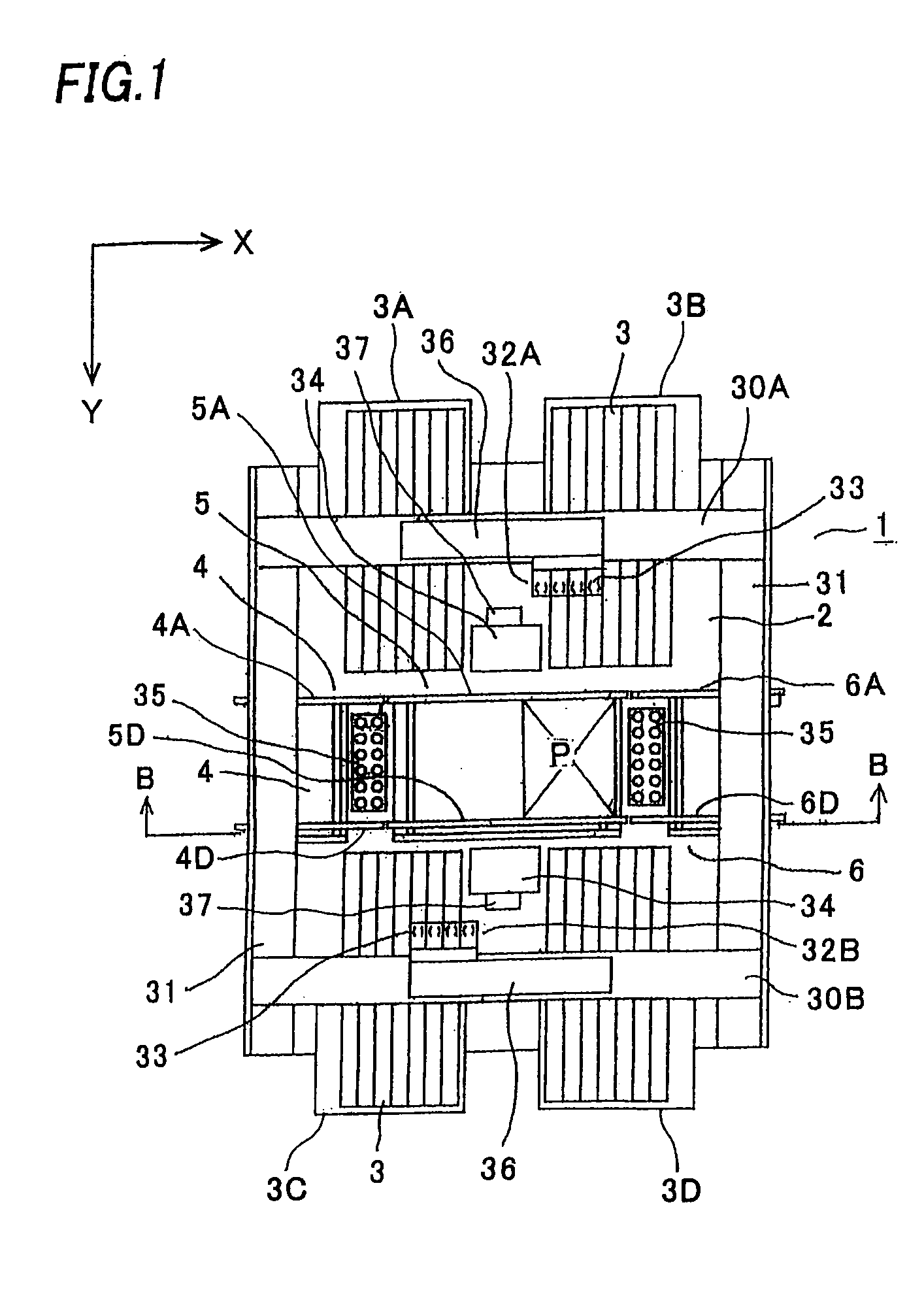
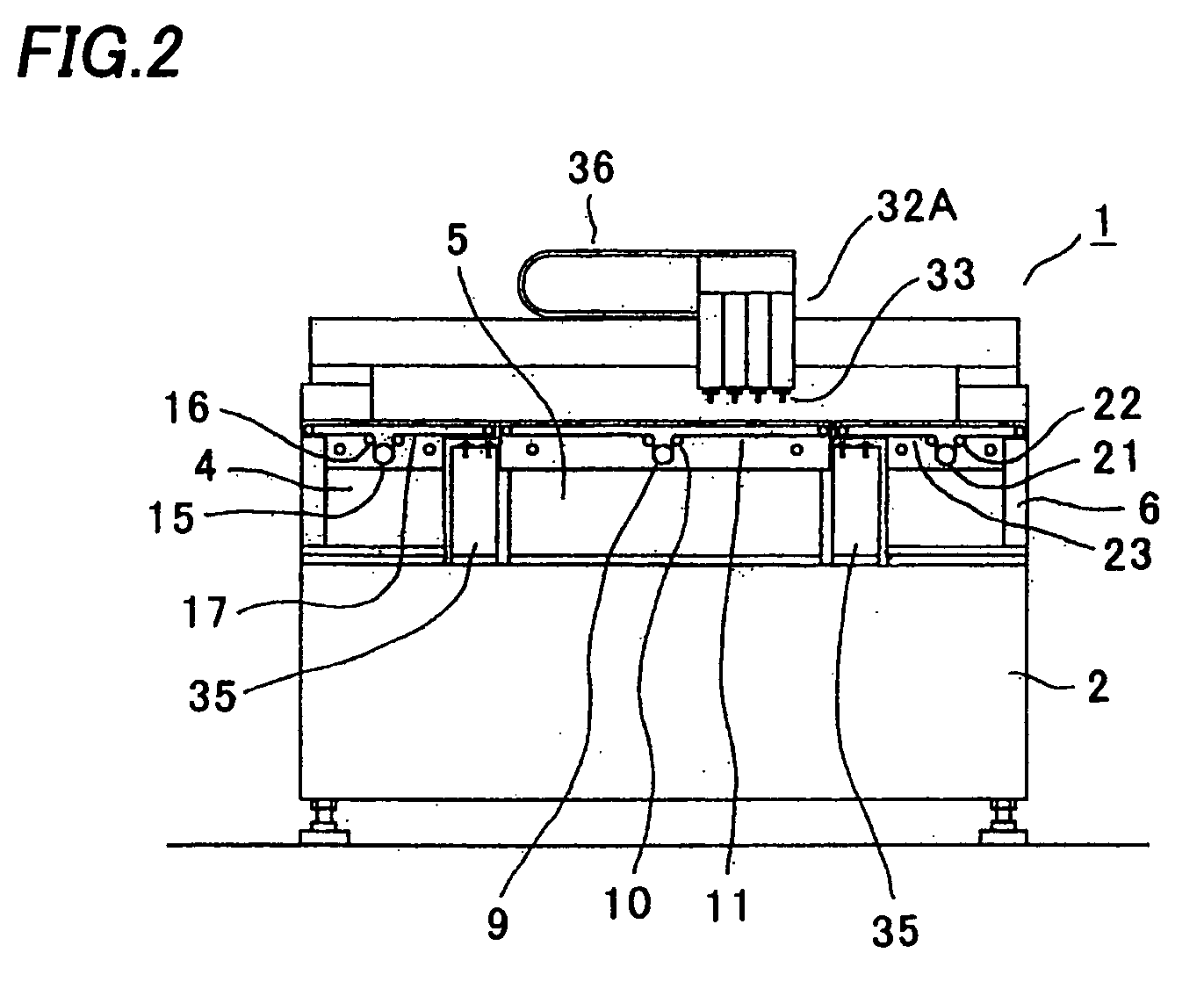
[0022] An embodiment of the invention will be described with reference to the drawings. FIG. 1 is a plan view of an electronic component mounting apparatus 1, and FIG. 2 is a cross-sectional view along line B-B of FIG. 1. A plurality of component feeding units 3 is detachably aligned and fixed on feeder bases 3A, 3B, 3C, and 3D on a base 2 of the electronic component mounting apparatus 1, and each of the component feeding units 3 feeds each of various electronic components to its component feeding position (component pick-up position) one by one.

[0023] A feed conveyer 4, a positioning portion 5, and a discharge conveyer 6 are provided on the base 2 between groups of the component feeding units 3 facing to each other. The feed conveyer 4 conveys a printed board P received from an upstream device (not shown) to the positioning portion 5, an electronic component is mounted on the printed board P positioned by a positioning device (not shown) in the positioning portion 5, and the print...


PUM

PropertyMeasurementUnit
Fractionaaaaaaaaaa

Abstract

When an electronic component is recognized to be improper and the CPU detects that a “component recognition monitoring navigation mode” is set for a component feeding unit feeding the component, the “component recognition monitoring navigation mode” is activated to shift to an adjustment mode and an operator decides whether or not the picked-up component is to be discharged by visually examining a component recognition image displayed on a CRT. When the judgment of the component as improper is correct upon the visual examination of the operator, the picked-up component is discarded and a picking-up operation is repeated. When the judgment is not correct, the component is not discarded, the illuminating condition is adjusted for the component and the component library data is corrected. After this correction, if linked, a component recognition test is executed and the library informing is performed.

Description

BACKGROUND OF THE INVENTION [0001] 1. Field of the Invention [0002] The invention relates to an electronic component mounting apparatus and a method for mounting electronic components on a printed board including picking the electronic components up from component feeding units by suction nozzles, taking images of the electronic components by a component recognition camera while illuminating the components by an illumination device, and performing recognition processing by a recognition processing device. [0003] 2. Description of the Related Art [0004] A conventional electronic component mounting method is disclosed in, for example, a Japanese Patent Application Publication No. 2000-136904. Generally, even when component library data having feature data of electronic components and so on are carefully formed, there are not many cases where component recognition processing is properly performed in practice, because of a mismatch between the components and an optical system or an illu...

Claims


Application Information

Patent Timeline
IPC IPC(8): G06T7/00H04N5/225G06T1/00H04N5/238H04N7/18H05K13/04H05K13/08
CPCH05K13/0413Y10T29/49131Y10T29/4913Y10T29/53178Y10T29/53191H05K13/0812H05K13/04
Inventor OYAMA, KAZUYOSHIFUKUSHIMA, HIDEAKI
Owner HITACHI HIGH TECH INSTR CO LTD
Learn More