
Pre-molded bifurcation insert

Active Publication Date: 2005-03-31
CR BARD INC
View PDF37 Cites 24 Cited by
  • Summary
  • Abstract
  • Description
  • Claims
  • Application Information

AI Technical Summary

Benefits of technology

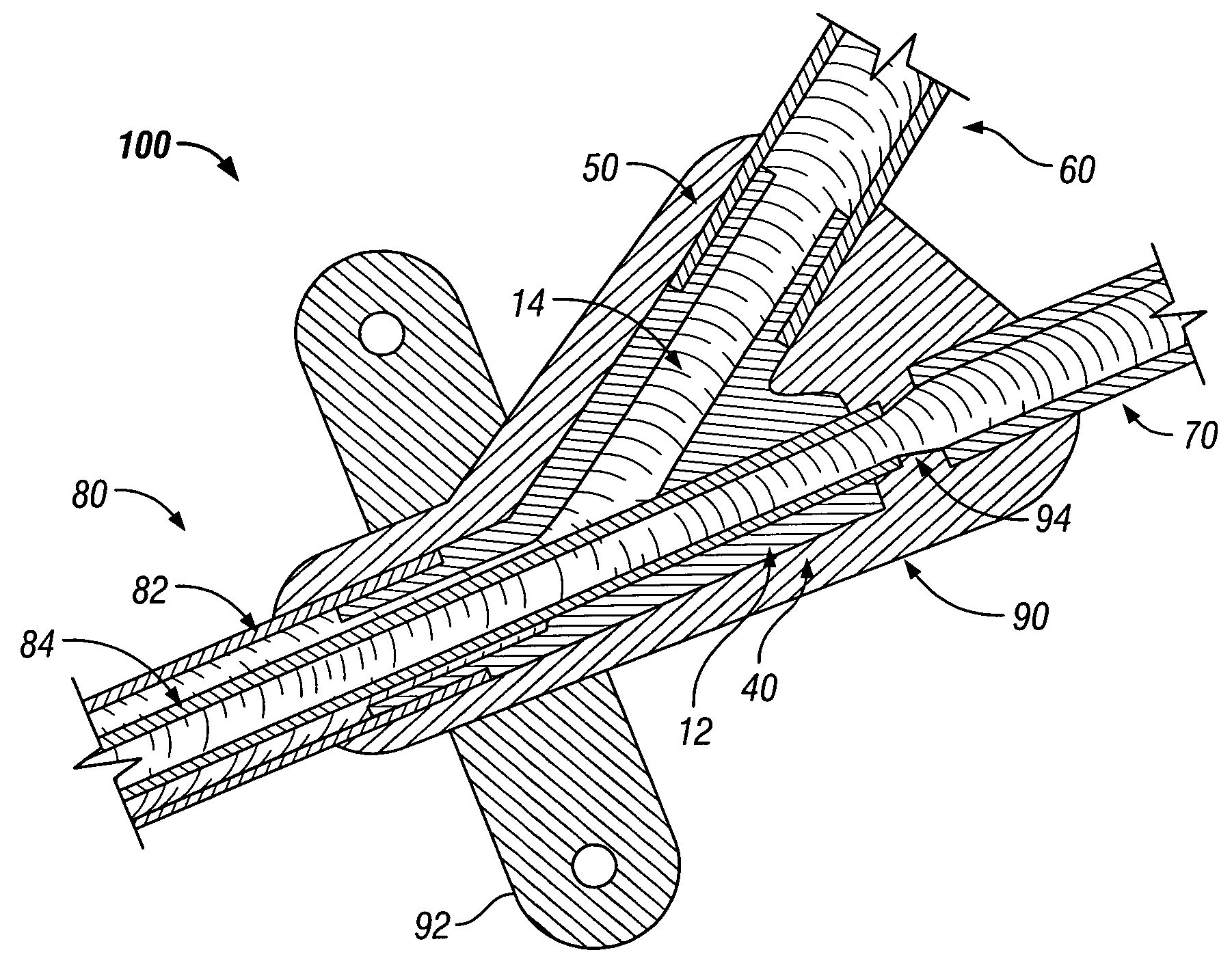
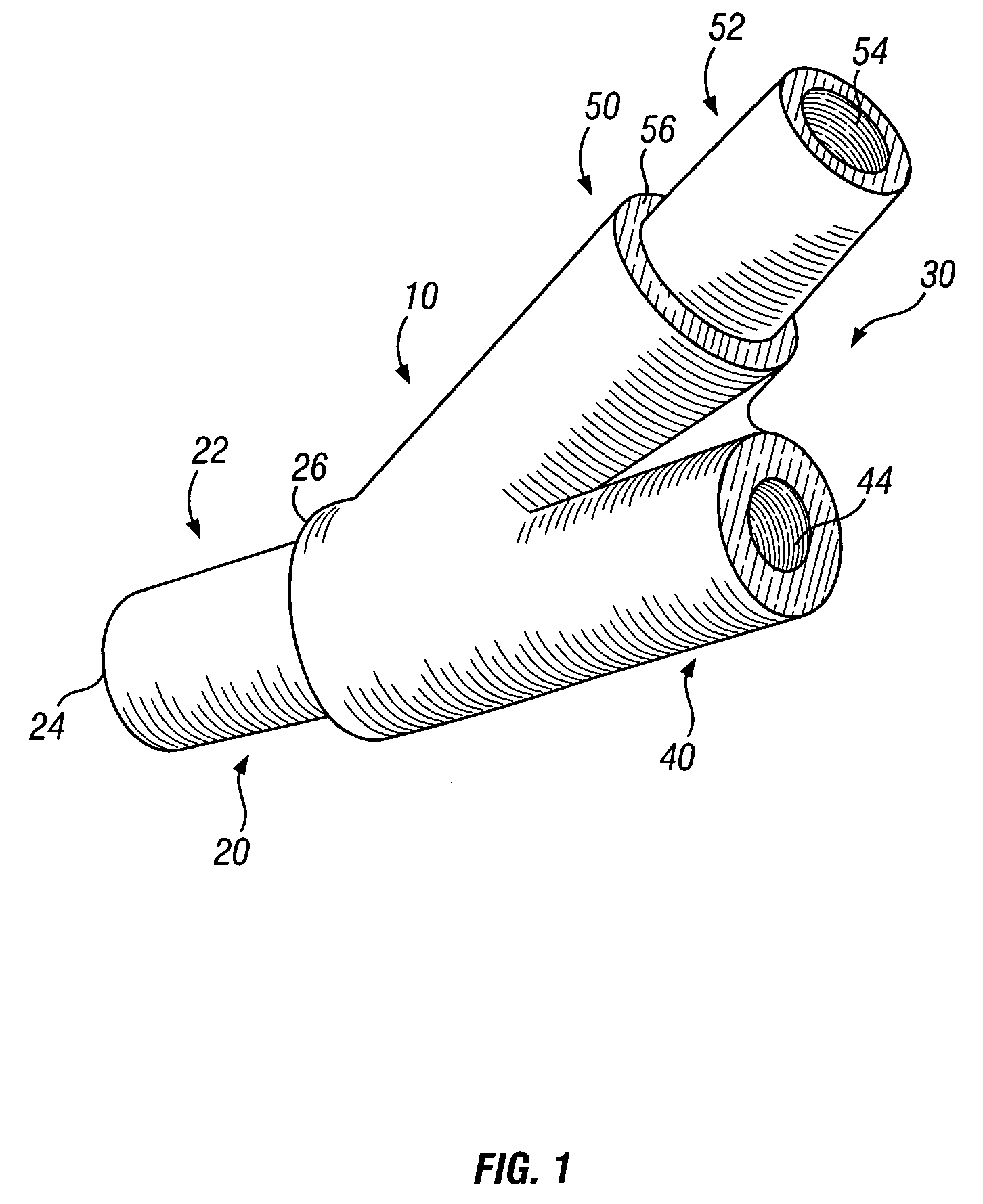
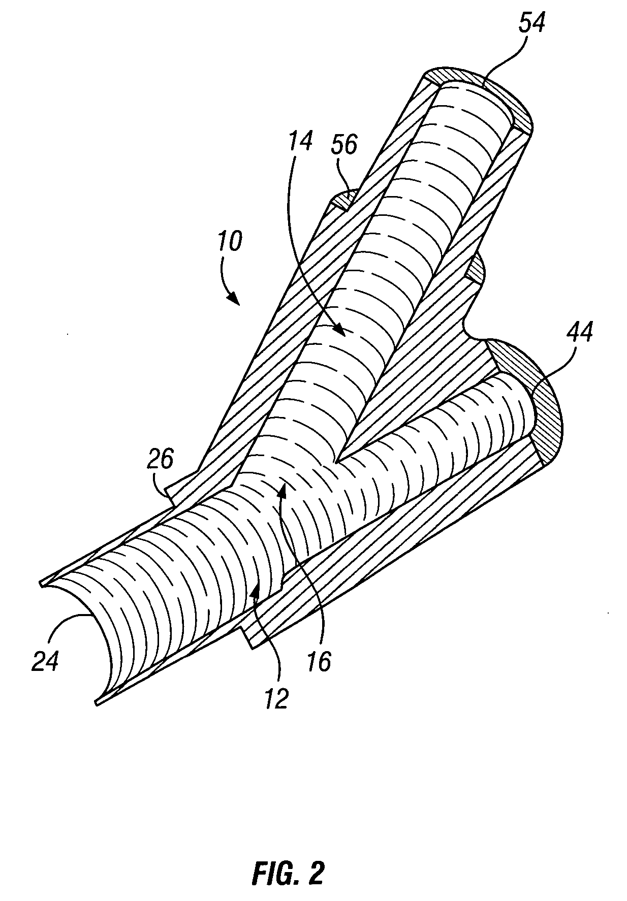
[0010] The present invention is directed to a bifurcation insert for coaxial catheters as well as a catheter assembly including a bifurcation insert. The bifurcation insert has a distal opening and two proximal openings, one each for the venous and arterial sides. Within the bifurcation insert is two passageways, a first extending from the distal opening to the venous side opening and the second extending from the first passageway to the arterial side opening. At the distal opening and arterial side opening, an outer wall is tapered, resulting in a shoulder so that placement within the outer lumen and first extension tube respectively is facilitated.

Problems solved by technology

There are drawbacks, however, to the above-described standard method.
First, use of a post-processing connection system for the extension tubing as opposed to overmolding the hub with the extension tubing in place, provides a much weaker connection and one that can become prone to detachment with higher flow rates.
Second, use of C-shape rods in the overmolding process can result in flow disturbances and inefficiencies in a functioning catheter, as well as the formation of bubbles, which causes turbulent flow.

Method used


Image

  • Pre-molded bifurcation insert
  • Pre-molded bifurcation insert
  • Pre-molded bifurcation insert

Examples


Embodiment Construction

[0016] The following detailed description should be read with reference to the drawings, in which like elements in different drawings are identically numbered. The drawings, which are not necessarily to scale, depict selected preferred embodiments and are not intended to limit the scope of the invention.

[0017] The detailed description illustrates by way of example, not by way of limitation, the principles of the invention. This description will clearly enable one skilled in the art to make and use the invention, and describes several embodiments, adaptations, variations, alternatives and uses of the invention, including what is presently believed to be the best mode of carrying out the invention.

[0018] The present invention satisfies the need for a bifurcation insert for coaxial catheters as an integral component of a multi-lumen catheter system, as well as the need for a reliable, efficient and uniform method of connecting a coaxial catheter to extension tubing. Although the bifu...


PUM


Abstract

A bifurcation insert for a coaxial catheter and a catheter assembly incorporating the bifurcation insert. The bifurcation insert contains an opening at a distal end and two openings in a proximal end, the distal end being configured for positioning within a proximal end of an outer lumen of the coaxial catheter. At the proximal end of the bifurcation insert, an arterial side is configured to receive a first extension tube, while a venous side is configured to receive a second extension tube. The catheter assembly incorporating the bifurcation insert includes a hub that is molded around the insert and properly positioned extension tubes and coaxial catheter such that each component is set into place with respect to one another.

Description

CROSS-REFERENCE TO RELATED APPLICATIONS [0001] Not applicable. STATEMENT REGARDING FEDERALLY SPONSORED RESEARCH OR DEVELOPMENT [0002] Not applicable. REFERENCE TO A COMPACT DISK APPENDIX [0003] Not applicable. BACKGROUND OF THE INVENTION [0004] Coaxial catheters are well-known in the art, being used for applications such as hemodialysis, where separate lumens are necessary to simultaneously remove blood from and return treated blood to a patient. Examples of coaxial catheters for use in hemodialysis treatments can be found in U.S. Pat. No. 5,976,103 to Martin. Such coaxial catheters, generally comprised of one or more inner catheters disposed within an outer catheter, are conventionally connected to extension tubing for the purpose of attachment to a dialysis or other treatment device. [0005] This is generally accomplished by molding a hub over the proximal end of the catheter, which transforms the coaxial configuration of the lumens to a side-by-side configuration so that the exten...

Claims


Application Information

Patent Timeline
IPC IPC(8): A61M25/00
CPCA61M25/0014A61M25/0028A61M2025/0039A61M2025/0031A61M25/0097A61M1/3661
Inventor TRIPLETT, DANIELWEINTRAUB, ROBERT
Owner CR BARD INC
Learn More