
Z-axis angular rate micro electro-mechanical systems (MEMS) sensor

Inactive Publication Date: 2005-03-31
KIONIX CORP
View PDF18 Cites 77 Cited by
  • Summary
  • Abstract
  • Description
  • Claims
  • Application Information

AI Technical Summary

Benefits of technology

The invention includes one or two proof masses suspended by a plurality of symmetric flexures connected to substrate anchor points. If two proof masses are utilized, there is also a flexure interconnecting the two proof masses with a much smaller spring constant than the main flexures of each proof mass, thus establishing a coupled oscillator system with an anti-phase normal mode.
Each proof mass includes a frame with an interior mass suspended by flexures which reacts as an accelerometer. The flexures from the substrate which are anchored to the frame are designed to flex

Problems solved by technology

Traditional military-grade gyroscope fabrication techniques are not scalable to high-volume low-cost manufacturing.
MEMS rate sensors have numerous technical challenges related to fabrication technique, electrical wiring, complex system control, minute sense signals, thermal variation, and ever-present error signals.

Method used


Image

  • Z-axis angular rate micro electro-mechanical systems (MEMS) sensor
  • Z-axis angular rate micro electro-mechanical systems (MEMS) sensor
  • Z-axis angular rate micro electro-mechanical systems (MEMS) sensor

Examples


first embodiment

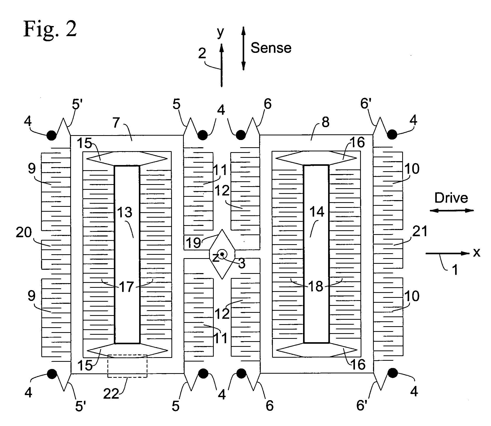
The present invention discloses a novel rate sensor design and system integration. In the first embodiment, the coupled-mass mechanical oscillator (210), shown schematically in FIG. 1, is realized with the necessary electrostatic drive and sense wiring to create the rate sensor of FIG. 2 by a novel fabrication process. The rate sensor is preferably fabricated using the methods taught in U.S. Pat. Nos. 6,239,473 (Adams et al.) and 6,342,430 (Adams et al.) assigned to an assignee of the present invention. These patents are hereby incorporated herein by reference. The fabrication process permits unique electrical isolation that allows released silicon beams to be electrically isolated but mechanically linked to other released beams and wafer substrates. Further, unique electrical “crossover” elements are also made possible whereby two mechanically intersecting and intact released silicon beams can propagate one electrical signal along the direction of one of the beams within the silico...

second embodiment

FIG. 4 shows the present invention, which contains a single oscillating proof-mass. The lack of a second coupled proof mass in FIG. 4 precludes common-mode cancellation of spurious acceleration. Such a simplified sensor has a lower manufacturing cost by virtue of less die area, suitable for applications requiring less-stringent rate and acceleration performance. The embodiment in FIG. 4 is symmetric about the x-axis (1) and y-axis (2) of the device. The x-axis (1) is the axis of driven proof-mass oscillation and the y-axis (2) is the axis of Coriolis-induced oscillation when the sensor is rotated about the z-axis (3). The released structure has anchor points (34) to the substrate generally exterior to the structure. A set of flexures (35) and (35′) connect a proof mass frame (37) to substrate anchor points (34). The flexures (35) and (35′) are designed to be compliant along the x-axis (1), but much stiffer along the y-axis (2) and z-axis (3).

Oscillation of the frame (37) and its in...


PUM


Abstract

An oscillatory angular rate MEMS sensor is described for sensing rotation about the “Z-axis”. Embodiments are either coupled-mass tuning-fork or single oscillating-mass in nature. The sensor includes mechanical and electrical function integration, and is preferably manufactured by a unique MEMS fabrication process.

Description

BACKGROUND OF THE INVENTION 1. Field of the Invention The invention pertains to the field of microdevices and microstructures. More particularly, the invention pertains to MEMS angular rate sensors. 2. Description of Related Art There is considerable interest in the development of low-cost, reliable, high-quality gyroscopic rate-of-rotation sensors enabled by developments in Micro Electro-Mechanical Systems (MEMS) technology. Traditional military-grade gyroscope fabrication techniques are not scalable to high-volume low-cost manufacturing. MEMS technology utilizes semiconductor fabrication techniques to construct microscopic electromechanical systems, and hence provides the manufacturing model for low-cost inertial sensing systems. A variety of researchers have pursued MEMS oscillatory rate gyroscope designs using a multiplicity of design and fabrication methods. All such designs, nevertheless, stem from fundamental oscillatory gyrodynamic principles, early embodied in U.S. Pat....

Claims


Application Information

Patent Timeline
IPC IPC(8): G01C19/56
CPCG01C19/5719
Inventor CHOJNACKI, ERIC P.SHEN-EPSTEIN, JUNE P.NENADIC, NENADSTIRLING, NATHAN L.NISTOR, VASILE
Owner KIONIX CORP
Learn More