
Process and apparatus for boiling and vaporizing multi-component fluids

a multi-component fluid and process technology, applied in mechanical equipment, steam engine plants, machines/engines, etc., can solve the problems of difficult to completely vaporize such multi-component fluids, so-called boiling crisis, drastic fall or reduction of film heat transfer coefficients

Inactive Publication Date: 2005-03-31
KALINA POWER LTD
View PDF28 Cites 6 Cited by
  • Summary
  • Abstract
  • Description
  • Claims
  • Application Information

AI Technical Summary

Benefits of technology

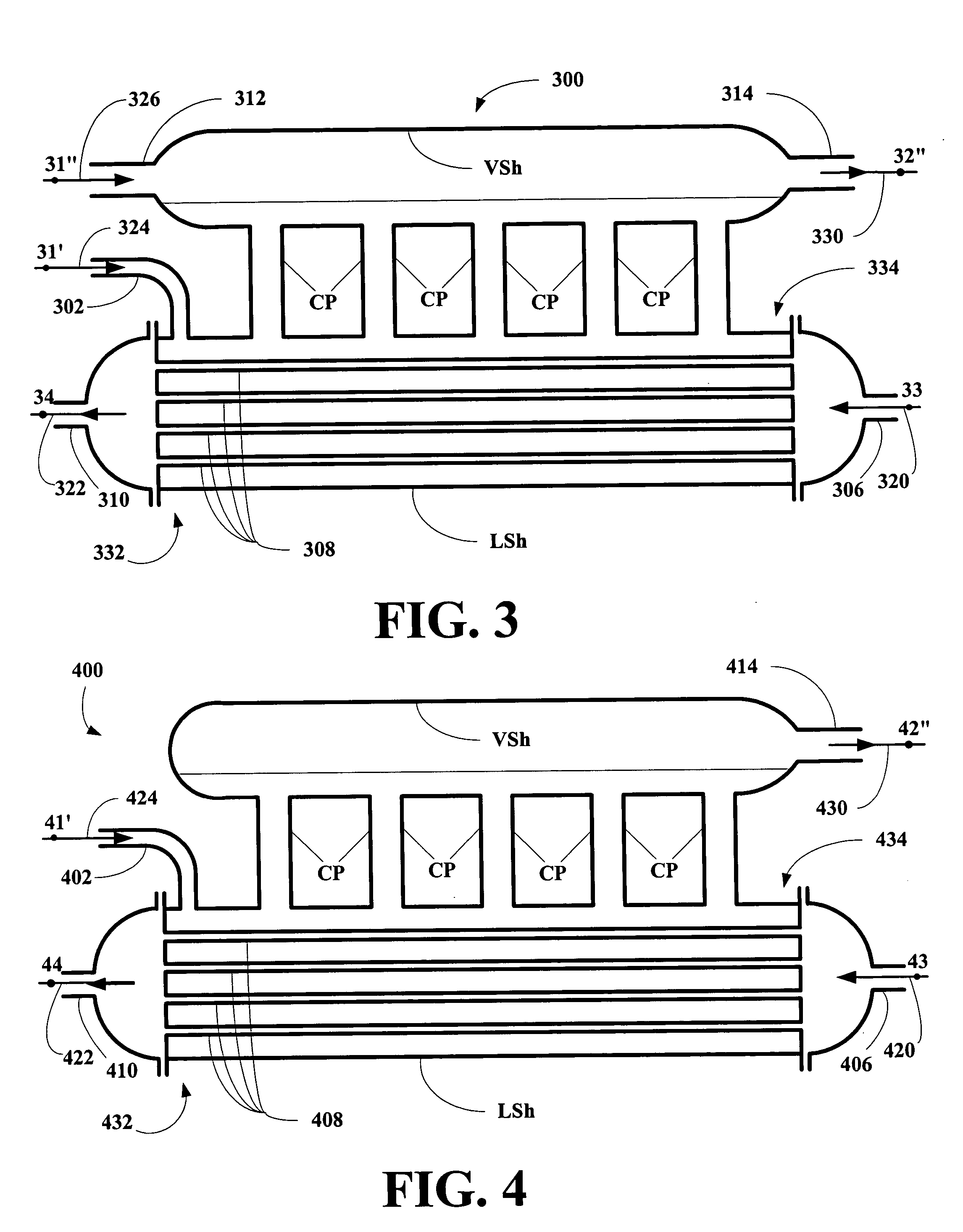
[0012] The present invention provides an improved boiler apparatus including a heat transfer unit and a vapor removal/equilibration apparatus, where the heat transfer unit and the vapor removal/equilibration unit are configured in such as way as to support substantially nucleate boiling throughout the heat transfer unit and to ensure

Problems solved by technology

However, it is, in practice difficult to completely vaporize such multi-component fluid.
Nucleate boiling has a very high film heat transfer coefficient, but as vapor accumulates, a so-called crisis of boiling occurs.
This crisis of boiling results in a drastic fall or reduction in the film heat transfer coefficient.
But, such an approach cannot be used with multi-component fluids, because the vapor produced will have a different composition (enriched by the low boiling component) than the remaining liquid resulting in a continuous composition profile across the heat exchanger with the concurrent crises of boiling.
Thus, if a multi-component fluid needs to be vaporized fully, the in a significant proportion of this vaporization process, i.e., inside the heat exchanger or boiler, nucleate boiling cannot be maintained.
Thus, the film heat transfer coefficient in such a process is very low.
This results in a very large increase in the required surface of the heat exchanger or boiler.
If complete vaporization of a multi-component working fluid has to be performed at high temperature, e.g., in a furnace of a power plant, then the inability of the process to maintain nucleate boiling inside heat transfer tubes of the furnace makes such a process technically very difficult.
However, because in the process of direct vaporization of multi-component working fluids where nucleate boiling cannot be maintained, the heat transfer tubes can achieve unacceptably high temperatures resulting in tube damage or destruction.

Method used


Image

  • Process and apparatus for boiling and vaporizing multi-component fluids
  • Process and apparatus for boiling and vaporizing multi-component fluids
  • Process and apparatus for boiling and vaporizing multi-component fluids

Examples


Embodiment Construction

[0024] The inventors have found that a heat transfer apparatus can be constructed for substantially, fully vaporizing a working fluid comprising at least two components one component having a boiling point less than the other component or at least one lower boiling component and at least one higher boiling component, which includes a vapor removal system adapted to maintain substantially nucleate boiling in a boiling / vaporization zone of the apparatus.

[0025] The present invention broadly relates to an improved boiling apparatus for substantially completely vaporizing a multi-component fluid to obtain a desired vapor stream having a desired temperature and composition, where the boiling apparatus includes at least one heat transfer apparatus, where each heat transfer apparatus comprises a heat exchanger, heat transfer loop or mixture thereof and a vapor removal apparatus. The removal of vapor at each heat transfer stage maintains nucleate boiling in each of the heat transfer apparat...


PUM


Abstract

A new boiler or heat transfer apparatus is disclosed for use with multi-component working fluids which includes a vapor removal apparatus designed to maintain a substantial compositional identity between the boiling liquid and its vapor along a length of the apparatus resulting in the maintenance of substantially nucleate boiling along the entire length of the apparatus. Systems incorporating the apparatus and methods for making and using the apparatus are also disclosed.

Description

BACKGROUND OF THE INVENTION [0001] 1. Field of the Invention [0002] The present invention relates to an improved boiler apparatus, systems incorporating the boiler apparatus and to methods for making and using the boiler apparatus and systems incorporating the boiler apparatus. [0003] More particularly, the present invention relates to an improved boiler apparatus, systems incorporating the boiler apparatus and to methods for making and using the boiler apparatus and systems incorporating the boiler apparatus, where the boiler apparatus includes a vapor removal unit that remove vapor as it boils so that the boiling throughout boiler's length remains substantially nucleate boiling. [0004] 2. Description of the Related Art [0005] In several processes and especially in power systems using multi-component working fluids, it is necessary to completely vaporize such multi-component fluids. However, it is, in practice difficult to completely vaporize such multi-component fluid. [0006] When...

Claims


Application Information

Patent Timeline
IPC IPC(8): F01K25/06
CPCF01K25/06
Inventor KALINA, ALEXANDER I.
Owner KALINA POWER LTD
Learn More