
Stapedial prosthesis and method of implanting the same

Inactive Publication Date: 2005-03-24
CLARITY
View PDF40 Cites 7 Cited by
  • Summary
  • Abstract
  • Description
  • Claims
  • Application Information

AI Technical Summary

Benefits of technology

[0022] It is another object of the invention to provide a stapedial prosthesis which facilitates manufacture, assembly and surgical implantation.
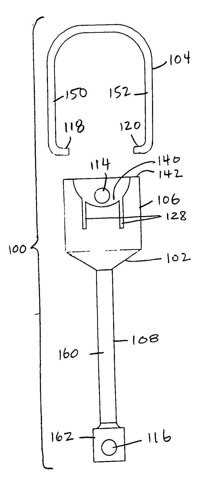
[0030] In accord with a third preferred aspect of the invention, visualization of the prosthesis during implantation is aided by providing a shaft portion of the device with a central portion having a relative smaller diameter than a distal end portion which attaches to or adjacent the anatomical oval window. This change in dimension provides a visual cue for the surgeon as the surgeon places the prosthesis into the opening made in the oval window. The smaller diameter central portion of the shaft also helps to reduce the mass of the device thus aiding in the sound energy transmission from the tympanic membrane to the inner ear.

Problems solved by technology

If the bail should rotate downwardly, out of range of contact with the incus, the prosthesis may become dislodged and extrusion may result.
In contrast, with a crimpable wire-crook prosthesis, a short term risk is that the prosthesis will fracture the incus.
Additionally, a loose fitting crimpable prosthesis may erode or wear away the incus from irregular loose vibration.
Thus, the challenge of stapedial prostheses, whether a bucket-and-bail type or a crimpable type is to secure the prosthesis sufficiently well to the incus to avoid its failing out of position while being careful not to have a connection to the incus that allows the incus to erode or to fracture.
Current attachment methods of the bail handle to the bucket in bail-and-bucket device require that the bucket handle protrude into the bucket of the prosthesis, thus disturbing the incus process as it lies in the bucket, which further creates problems in measuring the prosthesis bucket for a correct fit.
This securement method results in a variability of size and maneuverability in the bail handle, which further complicates the surgical insertion of the device.
The minute size of the prostheses also makes them extremely difficult to manipulate into proper position for tightening around the incus, even with state-of-the-art microsurgical instrumentation.
This is made more difficult as during the stapedectomy surgery, the view at the prosthesis insertion site is restricted.
Once in place, if the prosthesis is not tightened sufficiently about the incus, fluctuating hearing loss, dizziness, or extrusion of the prosthesis may occur.
If it is too tight, necrosis of the incus may occur.
In either case, the securement method in itself may cause trauma to the delicate middle ear structures, including fracture or subluxation (dislocation) of the incus.

Method used


Image

  • Stapedial prosthesis and method of implanting the same
  • Stapedial prosthesis and method of implanting the same
  • Stapedial prosthesis and method of implanting the same

Examples


Embodiment Construction

[0044] Referring to FIGS. 7 through 10, a preferred embodiment of a stapedial prosthesis 100 includes a body 102 and a bail handle 104. The body 102 is preferably constructed from commercially pure Grade 2 titanium, and is further defined by a closed-bottom bowl shaped cavity, termed the bucket 106 (or well), which tapers down to a shaft 108 (also termed a stem or a rod). The bucket 106 of the body 102 is sized to accept the long process and lenticular process of the incus. The body 102 of the prosthesis 100 preferably defines four holes 110, 112, 114, 116, each designed for a specific purpose as now described. The two diametrically-opposed holes 110, 112 near the bottom of the bucket 106 are receptacles (bail insert openings) for receiving ends 118, 120 of the bail handle 104, described below. The hole 114 located at the rear of the bucket 106 near the rim 142 is intended for positioning the prosthesis 100. That is, a surgeon can insert a pick 200 and turn the prosthesis 100 to ach...


PUM


Abstract

A stapedial prosthesis includes a body defining a bucket and a shaft, and a bail handle coupled to the bucket. The bucket is preferably adjustable in diameter to fit the incus lenticular process. The shaft preferably has a varying diameter, with a central portion of a smaller diameter than a distal portion which aids in depth perception during implantation and reduces mass to permit better sound energy transmission by the prosthesis. The bail handle is preferably spring-loaded and preferably constructed of titanium. The bail handle is preferably coupled to the body without crimping, twisting or welding and preferably biases the incus toward the bucket. A method of implanting a stapedial prosthesis is also provided.

Description

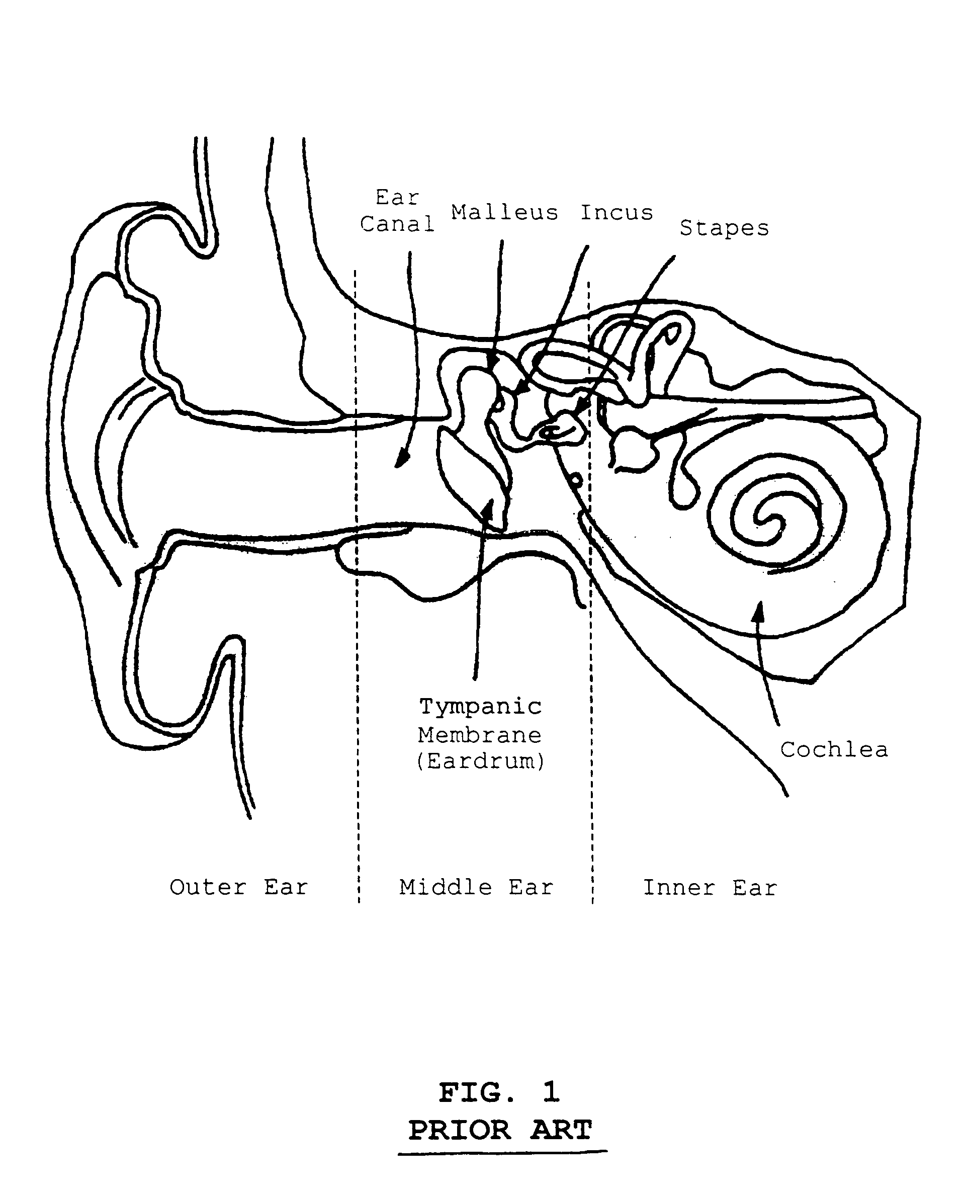
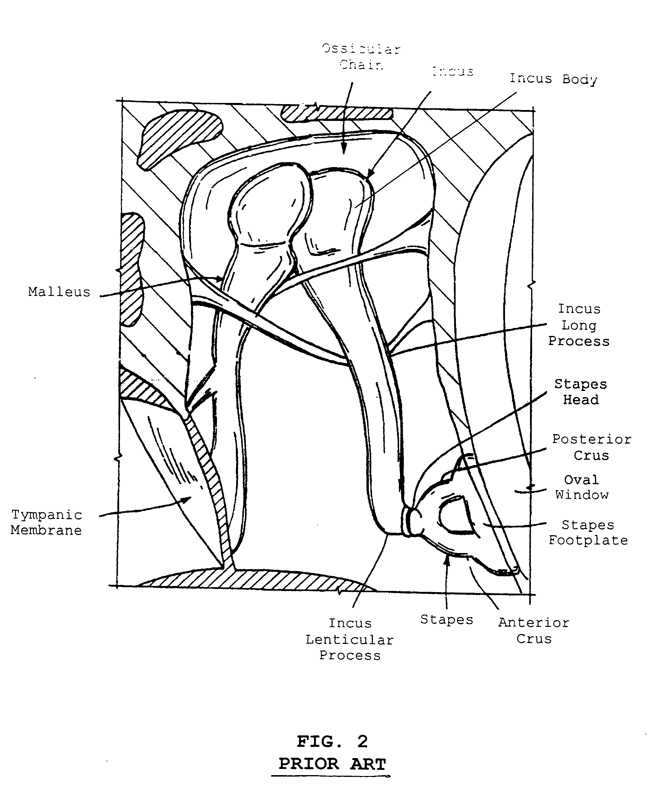
BACKGROUND [0001] 1. Field of Invention [0002] The present invention relates to ossicular prostheses, more particularly to an improved stapedial prosthesis. [0003] 2. State of the Art [0004] Medical Background: Stapes Diseases [0005] Referring to prior art FIGS. 1 and 2, in a normal ear, sound energy, which consists of vibrations of air molecules, is directed by the auricle, or outer ear, through the ear canal to the tympanic membrane. Movements of the tympanic membrane are transferred to the ossicles, or the ossicular chain of the bones of the middle ear: malleus, incus and stapes. These movements eventually reach the inner ear labyrinth fluids via the stapes, which rests in a small groove, commonly called the oval window. The oval window is in intimate contact with the inner ear fluids. The movement of the inner ear fluids then stimulates the fine sensory organs of the inner ear, which in turn stimulate the auditory nerve, finally transferring the original sound energy to the brai...

Claims


Application Information

Patent Timeline
IPC IPC(8): A61F2/18
CPCA61F2002/183A61F2/18
Inventor PRESCOTT, ANTHONY D.BARTELS, LOREN J.
Owner CLARITY
Learn More