
Electrical connector with mounting member and method of making same

a technology of mounting member and electrical connector, which is applied in the direction of coupling device connection, electrical discharge lamp, coupling device details, etc., can solve the problems of socket connector slanting away from the original position, soft solder ball, socket connector liable to lose balance, etc., to avoid the incidence of damage, enhance the attachment of the socket connector, and reduce the effect of soldering

Inactive Publication Date: 2005-03-24
HON HAI PRECISION IND CO LTD
View PDF5 Cites 4 Cited by
  • Summary
  • Abstract
  • Description
  • Claims
  • Application Information

AI Technical Summary

Benefits of technology

[0008] Accordingly, an object of the present invention is to provide a socket connector able to be stabilized on a side of a PCB as other component or components are mounted on the other side of the PCB in a heat environment.
[0009] Another object of the present invention is to provide a method of making the socket connector, thereby to avoid incidence of damage during assembly of a mounting member onto a base of the socket connector.
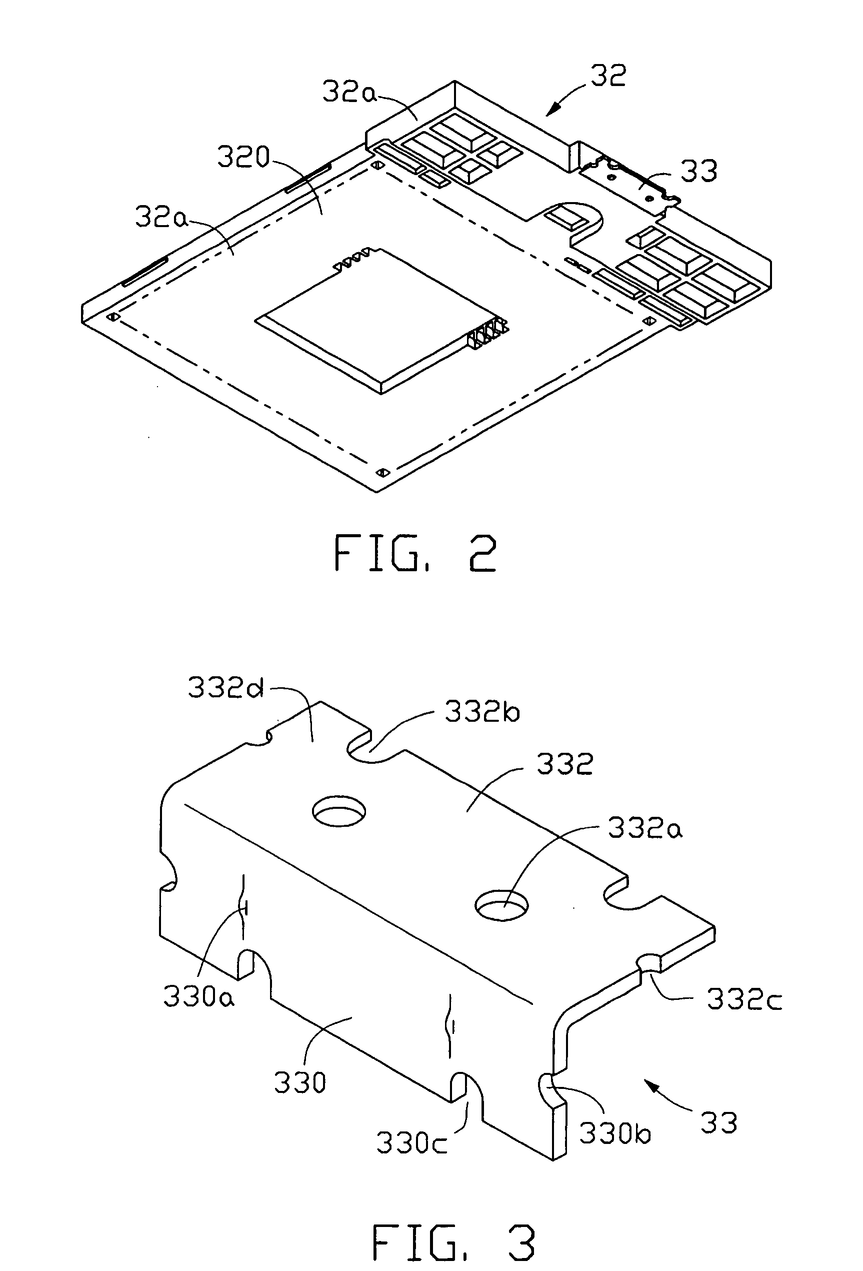
[0010] To fulfill the above objects, a socket connector is applied according to the present invention. The socket connector comprises a base, a plurality of terminals received in the base, a cover slidably mounted on the base, an urging member embedded in the base and the cover for urging the cover to move relative to the base, and a mounting member molded onto the base. A solderable member is formed on each terminal, for being soldered on a PCB. The socket connector is thereby electrically attached to the PCB. Simultaneously, the mounting member has a relatively large soldering surface attached to the PCB, thereby to enhance attachment of the socket connector to the PCB.
[0011] Additionally, a method of molding the mounting member onto the base is also applied according to the present invention. The method comprises the following steps: forming the mounting member, positioning the mounting member into a base mold, closing the base mold, inserting plastic material into the base mold, cooling the base mold, separating the base mold, and extracting the formed base with a part of the mounting member molded onto the formed base. The mounting member is safely molded and attached to the base, thereby to avoid incidence of damage during insertion of the mounting member onto the base of the socket connector.

Problems solved by technology

Said high temperature is prone to soft the solder balls, through which the socket connector is mounted on the side of the PCB.
If this happens, the socket connector is liable to lose balance and slant away from the original position.

Method used


Image

  • Electrical connector with mounting member and method of making same
  • Electrical connector with mounting member and method of making same
  • Electrical connector with mounting member and method of making same

Examples


Embodiment Construction

[0031] Reference is now made to the drawings to describe the invention in detail.

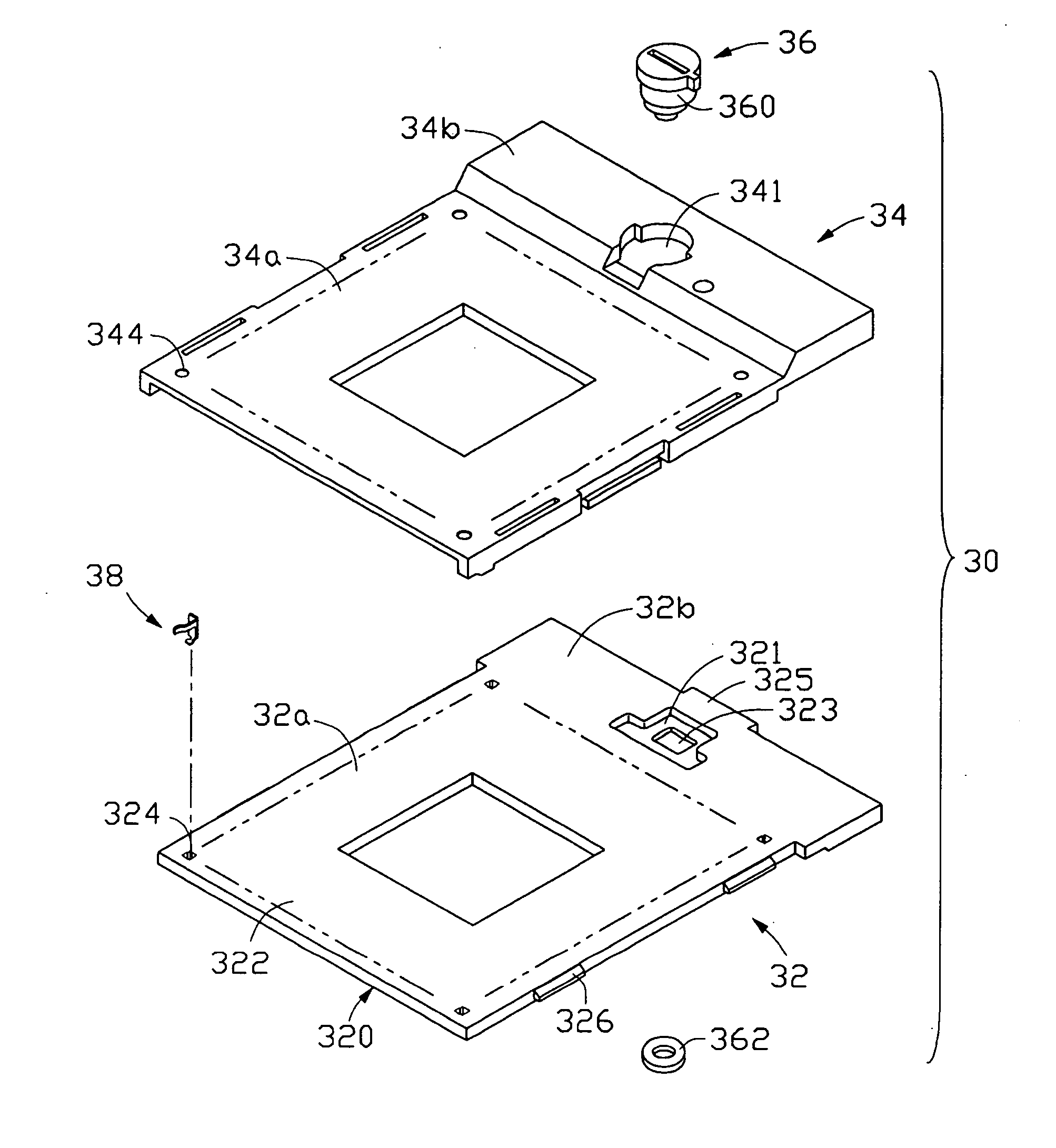
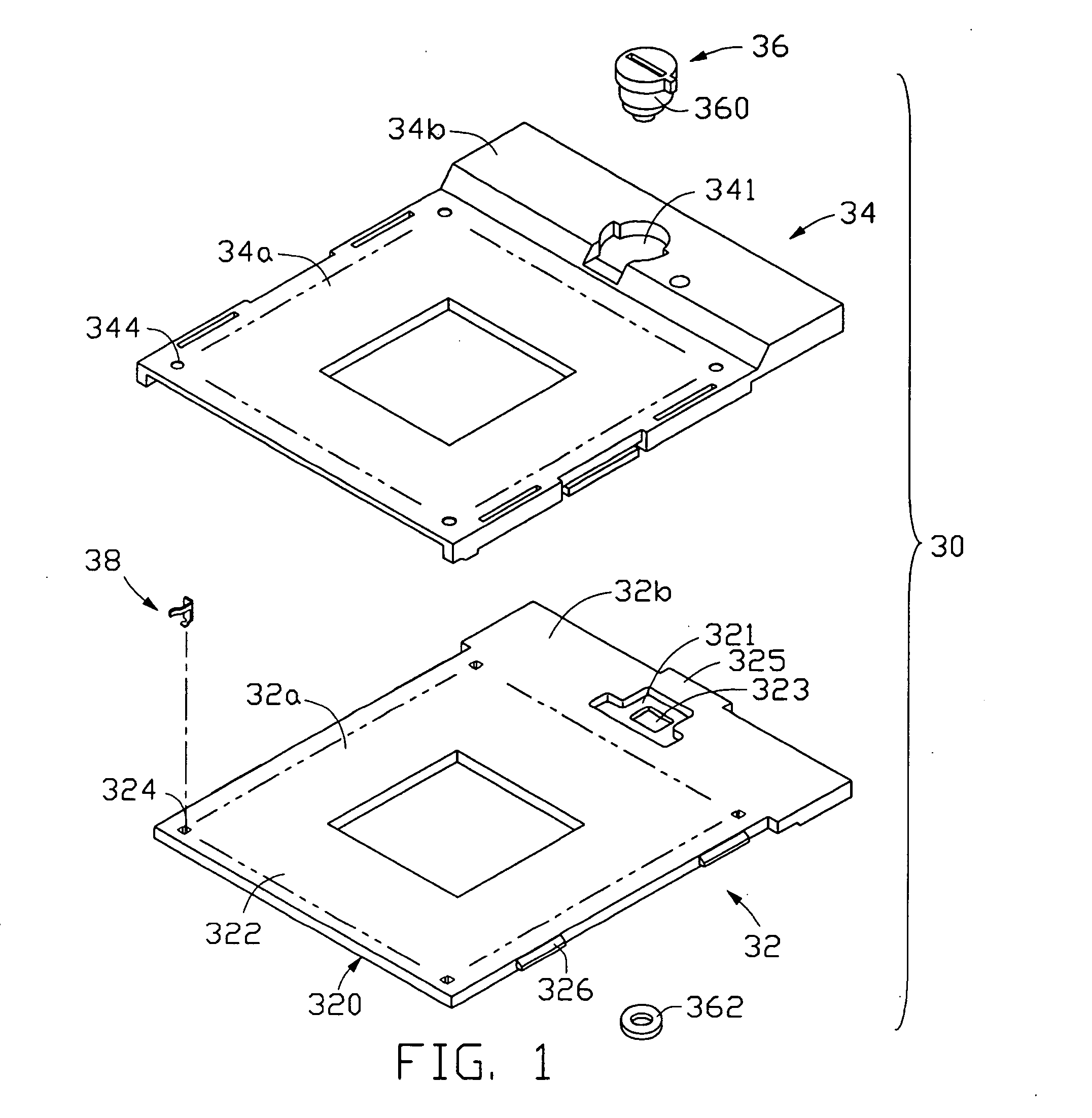
[0032] Referring to FIG. 1, there is shown an exploded, isometric view of a socket connector 30 according to the present invention. The socket connector 30 is mainly applied for electrically interconnecting an IC package, such as a CPU, with a PCB 40. The socket connector 30 is mounted on the PCB 40 via surface mounting technology (SMT). The socket connector 30 comprises a parallelepiped dielectric base 32, a plate like dielectric cover 34 slidably mounted on the base 32, a plurality of terminals 38 secured in the base 32, an driving mechanism 36 transplanted in the base 32 and the cover 34.

[0033] The base 32 comprises a rectangular plate like first body 32a and a first head portion 32b extending from one end of the first body 32a.

[0034] A mounting surface 320 is defined on the base 32 toward the PCB 40. A mating surface 322 is defined on the base 32 opposite the mounting surface 320, for supporting ...


PUM


Abstract

A socket connector (30) comprises a base (32) with a mounting member (33) molded onto the base. The mounted member can be soldered on a PCB (40), thereby to secure the socket connector on the PCB. Additionally, a method of molding the mounting member onto the base comprises the following steps: forming the mounting member, positioning the mounting member in a base mold (70) having an upper mold (70a) and a lower mold (70b), closing the upper mold and the lower mold, inserting plastic material into the base mold, cooling the base mold, separating the upper mold and the lower mold, extracting the formed base with a part of the mounting member molded into the housing. The mounting member is molded onto the base, thereby to avoid incidence of damage during insertion of the mounting member onto the base.

Description

BACKGROUND OF THE INVENTION [0001] 1. Field of the Invention [0002] The present invention relates to the art of electrical connectors and to the art of methods of making the electrical connectors, and more particularly to a socket connector to be soldered on a printed circuit board (PCB) and to a method of making the socket connector. [0003] 2. Description of the Prior Art [0004] With the trend toward high-density of conductive terminals in socket connectors, many socket connectors are electrically attached to a substrate, such as a PCB, generally via ball grid array (BGA) type package. This solution can reduce a terminal pitch to 0.050 inch. Except for the socket connectors, the PCB simultaneously carries other components in order to enhance integrated characteristics of the PCB. When a BGA-type socket connector has first been mounted on a side of the PCB, other components are consequently soldered on the other side of the PCB in a high temperature environment. Said high temperatur...

Claims


Application Information

Patent Timeline
Patent Type & Authority Applications(United States)
IPC IPC(8): H01R33/74H01R43/24
CPCH01R12/707H01R43/24
Inventor TAN, SHIJIE
Owner HON HAI PRECISION IND CO LTD
Learn More