High speed large core multimode fiber optic transmission system and method therefore
- Summary
- Abstract
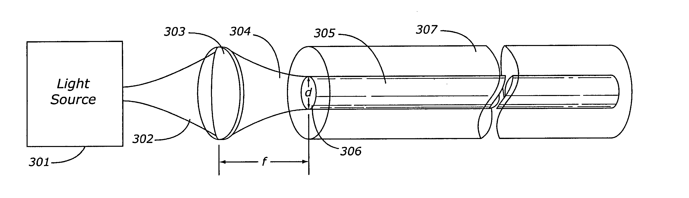
- Description
- Claims
- Application Information
AI Technical Summary
Benefits of technology
Problems solved by technology
Method used
Image

Examples
Embodiment Construction
The following detailed description is merely exemplary in nature and is not intended to limit the invention or the application and uses of the invention. Furthermore, there is no intention to be bound by any expressed or implied theory presented in the preceding technical field, background, brief summary or the following detailed description.
The cost and complexity of using single mode fiber optic cable is a significant factor in many business decisions. Single mode fiber optic cable is still the primary fiber optic of choice for extremely high speeds or where the cable is extended over a long distance. A large number of fiber optic applications fall in the low to medium distance range. An upper end of this range is approximately a 1 kilometer connection. Local area networks for business or home connections for a digital cable company are two well know high volume applications for fiber optic cable. Another application is related to the aerospace industry. Open avionics architect...
PUM
 Abstract
Description
Claims
Application Information
 - R&D
- Intellectual Property
- Life Sciences
- Materials
- Tech Scout
- Unparalleled Data Quality
- Higher Quality Content
- 60% Fewer Hallucinations
Browse by: Latest US Patents, China's latest patents, Technical Efficacy Thesaurus, Application Domain, Technology Topic, Popular Technical Reports.
© 2025 PatSnap. All rights reserved.Legal|Privacy policy|Modern Slavery Act Transparency Statement|Sitemap|About US| Contact US: help@patsnap.com