Display device

a display device and flat panel technology, applied in the field of flat panel display devices, can solve problems such as display defects, and achieve the effects of preventing the application of stress, reducing the effect of external impact, and reducing the impact resistan

Inactive Publication Date: 2005-03-24
HITACHI DISPLAYS
View PDF7 Cites 50 Cited by
  • Summary
  • Abstract
  • Description
  • Claims
  • Application Information

AI Technical Summary

Benefits of technology

[0010] As seen in FIG. 9, one surface (an upper surface) of the rubber cushion GC1, which is interposed between a glass substrate of the liquid crystal display panel PNL and the upper frame SHD, is fixed to the upper frame SHD side using an adhesive agent or an adhesive tape, while a gap (clearance) C of 0.2 mm to 0.4 mm, for example, is formed between the other surface of the rubber cushion GC1 and the glass substrate of the liquid crystal display panel PNL. As described above, this gap C performs a function of absorbing the warp of the liquid crystal display panel PNL attributed to environmental conditions, thus preventing a stress from being applied to a display region of the liquid crystal display panel PNL.
[0017] According to the present invention, by always ensuring sealing between a plurality of plate-like members, including the display panel, which are arranged in a stacked manner, or between sheet-like members or frame-like members, by using the elastic function of the shape elastic member, even when the members suffer from deformation, such as warping or the like, it is possible to prevent the intrusion of a foreign substance at the position where the shape elastic member is arranged. Further, according to the present invention, due to the interposition of the shape elastic member, the application of a local stress can be obviated, thus also alleviating damage caused by external impact.

Problems solved by technology

As a result, dotted black shades will appear in the illumination light, thus causing a defective display.
Further, a foreign substance may also intrudethrough a gap between the liquid crystal display panel PNL and the rubber cushion GC1 of the upper frame SHD, and this foreign substance remains in the inside of the casing, thus giving rise to various drawbacks.
Although the drawback attributed to the intrusion of a foreign substance in the liquid crystal display device has been described above, another display device, for example, a display device having no backlight, such as an organic EL display device, a FED display device and the like, also has the following drawback.

Method used


Image

  • Display device
  • Display device
  • Display device

Examples


embodiment 1

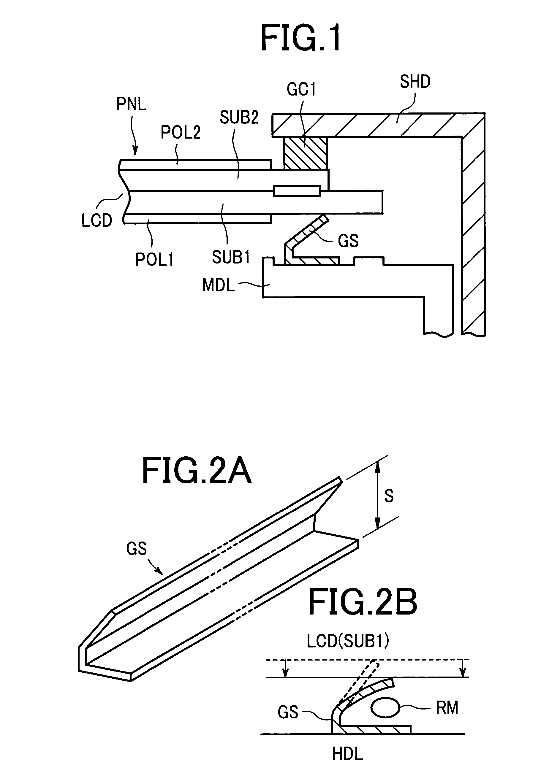
[0029]FIG. 1 is a diagram showing an embodiment 1 of the present invention in the form of a cross-sectional view of the structure of a representative part of the basic constitution of the present invention. In FIG. 1, with respect to the backlight device that has already been explained in conjunction with FIG. 9, only the mold MDL is shown, and the light guide plate and the like are omitted from the drawing. Further, the optical compensation sheet mounted on the light guide plate is also omitted from the drawing. A liquid crystal display panel PNL is configured such that a liquid crystal cell LCD is formed by sealing liquid crystal between a pair of glass substrates SUB1, SUB2, and polarizers POL1, POL2 are respectively laminated to a back surface and a front surface of the liquid crystal cell LCD. The liquid crystal display panel PNL is mounted on the backlight device, and a shaped elastic member GS is interposed between the liquid crystal display panel PNL and the mold MDL of the ...

embodiment 2

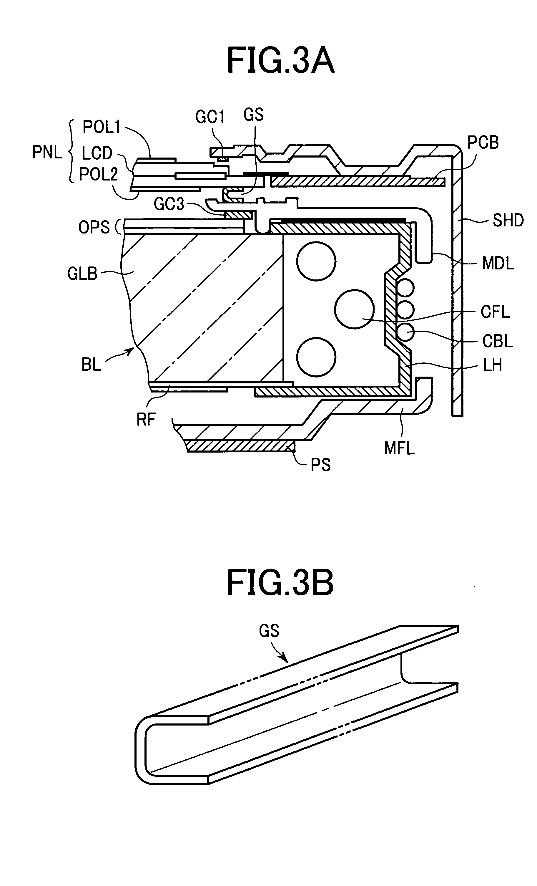
[0035]FIG. 3A and FIG. 3B are views of a liquid crystal display device representing an embodiment 2 of the present invention, wherein FIG. 3A is a cross-sectional view of a representative part in the same manner as FIG. 9, and FIG. 3B is a perspective view of the shaped elastic member of this embodiment. The entire constitution of this embodiment is substantially the same as the constitution shown in FIG. 9, except for the shaped elastic member, which is interposed between the liquid crystal display panel PNL and the backlight device. Accordingly, a repeated explanation thereof is omitted unless otherwise necessary.

[0036] The embodiment shown in FIG. 3A differs from the embodiment 1 with respect to the point that the shaped elastic member GS, which is interposed between the liquid crystal display panel PNL and the backlight device, has a U-shaped cross section, as shown in FIG. 3B. This shaped elastic member GS, having a U-shaped cross-section, may be manufactured by bending a stri...

embodiment 3

[0038]FIG. 4A and FIG. 4B are views of a liquid crystal display device representing an embodiment 3 of the present invention, wherein FIG. 4A is a cross-sectional view of a representative part in the same manner as FIG. 9, and FIG. 4B is a perspective view of the shaped elastic member of this embodiment. The entire constitution of this embodiment is substantially the same as the constitution shown in FIG. 9, except for the shaped elastic member, which is interposed between the liquid crystal display panel PNL and the backlight device. Accordingly, a repeated explanation thereof is omitted unless otherwise necessary.

[0039] The shaped elastic member GS of this embodiment has a circular cross section, thus forming a circular tubular body, wherein one longitudinal side surface (lower side surface) of the shaped elastic member GS is fixedly mounted on an optical compensation sheet OPS that is mounted on a backlight device using an adhesive agent or an adhesive tape. On the other hand, t...


PUM

PropertyMeasurementUnit
heightaaaaaaaaaa
heightaaaaaaaaaa
widthaaaaaaaaaa

Abstract

A defective display is obviated by preventing the intrusion of a foreign substance in a gap defined between a constitutional member, such as an upper frame, an intermediate frame, a backlight device or the like, and a display panel and by suppressing the application of a stress to the display panel. A shaped elastic member is interposed between a liquid crystal display panel and a mold of a backlight device. One longitudinal side surface of the shaped elastic member is fixedly mounted on the backlight device and the other longitudinal side surface of the shaped elastic member is non-fixedly mounted on the liquid crystal display panel, such that the other longitudinal side surface is always brought into contact with the liquid crystal display panel to prevent the generation of a gap therebetween.

Description

BACKGROUND OF THE INVENTION [0001] The present invention relates to a flat panel type display device using a display panel; and, more particularly, the invention relates to a display device which obviates the appearance of a display defect by preventing the intrusion of a foreign substance between an upper frame, an intermediate frame or the like, which constitutes a casing of the display device, and a display panel, and / or by suppressing the application of a stress to the display panel attributed to environmental conditions. [0002] As a display device which is capable of producing a high-definition color display for a notebook type computer or a display monitor, a flat panel type display device has been put into practice or has been studied for future practical use. As such a flat panel type display device, various display devices, including a liquid crystal display device which uses a liquid crystal display panel, an organic electroluminescence display device (an organic EL displa...

Claims


Application Information

Patent Timeline
Patent Type & Authority Applications(United States)
IPC IPC(8): G02F1/1333G02F1/13G09F9/00
CPCG02F2201/503G02F1/133308
Inventor FUKAYAMA, NORIHISATANAKA, KAZUYOSHI
Owner HITACHI DISPLAYS
Why Eureka
Try Eureka