
Input device

a technology of input device and sleep mode, which is applied in the direction of liquid/fluent solid measurement, instruments, high-level techniques, etc., can solve the problems of disadvantageous complexity of circuitry and control, impair operability, etc., and achieve simplified circuitry and reliable disassembly and simple operation.

Inactive Publication Date: 2005-03-17
ALPS ALPINE CO LTD
View PDF5 Cites 6 Cited by
  • Summary
  • Abstract
  • Description
  • Claims
  • Application Information

AI Technical Summary

Benefits of technology

[0009] It is an object of the present invention to provide an input device which can reliably disable a sleep mode without impairing the operability and which has simplified circuitry.
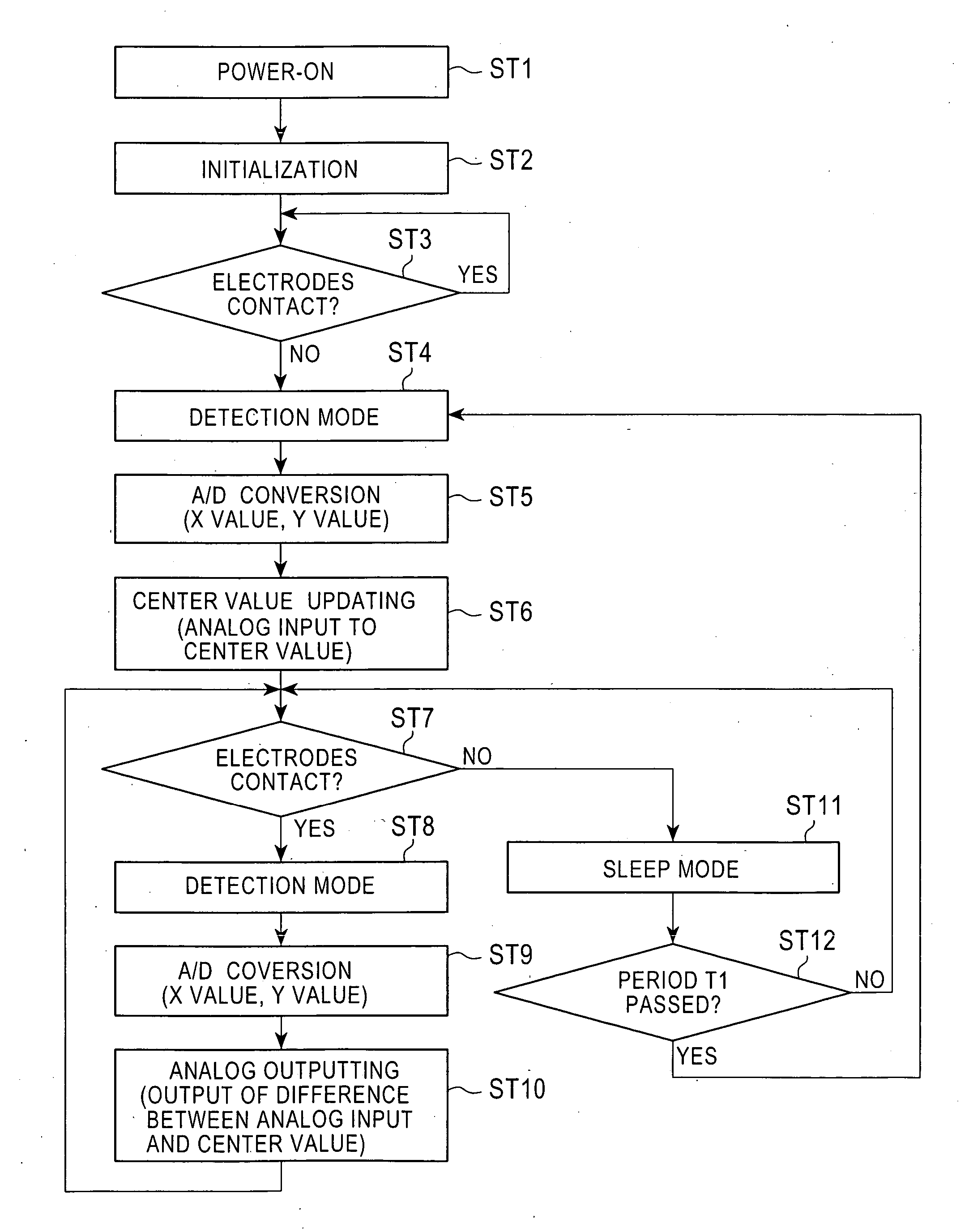
[0010] The input device according to the present invention preferably includes contacts having resistive elements and low-resistance elements opposing the respective resistive elements, an operating unit varying the contact areas between the low-resistance elements and the resistive elements, and detecting means for switching an operation mode of the input device, without using the contacts, in response to operations of the operating unit. When the operating unit is not operated for a predetermined period, the detecting means preferably switches the operation mode to the sleep mode to reduce power consumption while the low-resistance elements and the respective resistive elements are kept in contact with each other. When the operating unit is operated, the detecting means preferably switches the operation mode and the sleep mode is disabled.
[0011] In the above-described invention, the low-resistance elements and the respective resistive elements are kept in contact with each other even when the operating unit is not operated. This arrangement prevents a dead band, and thus the operability is not impaired. Moreover, additional detecting means for disabling the sleep mode can reliably disable the sleep mode. Furthermore, since separate circuits are prepared for detecting operations in the sleep mode and in a normal operation mode, the circuitry can be simplified.

Problems solved by technology

This causes a ‘dead zone’ which impairs the operability when the arrangement is applied to an input device whose output varies in an analog fashion in response to the pushing force.
Furthermore, since one circuit is used for detecting operations both in the sleep mode and in a normal operation mode, the circuitry and the control are disadvantageously complicated.

Method used


Image

  • Input device
  • Input device
  • Input device

Examples


Embodiment Construction

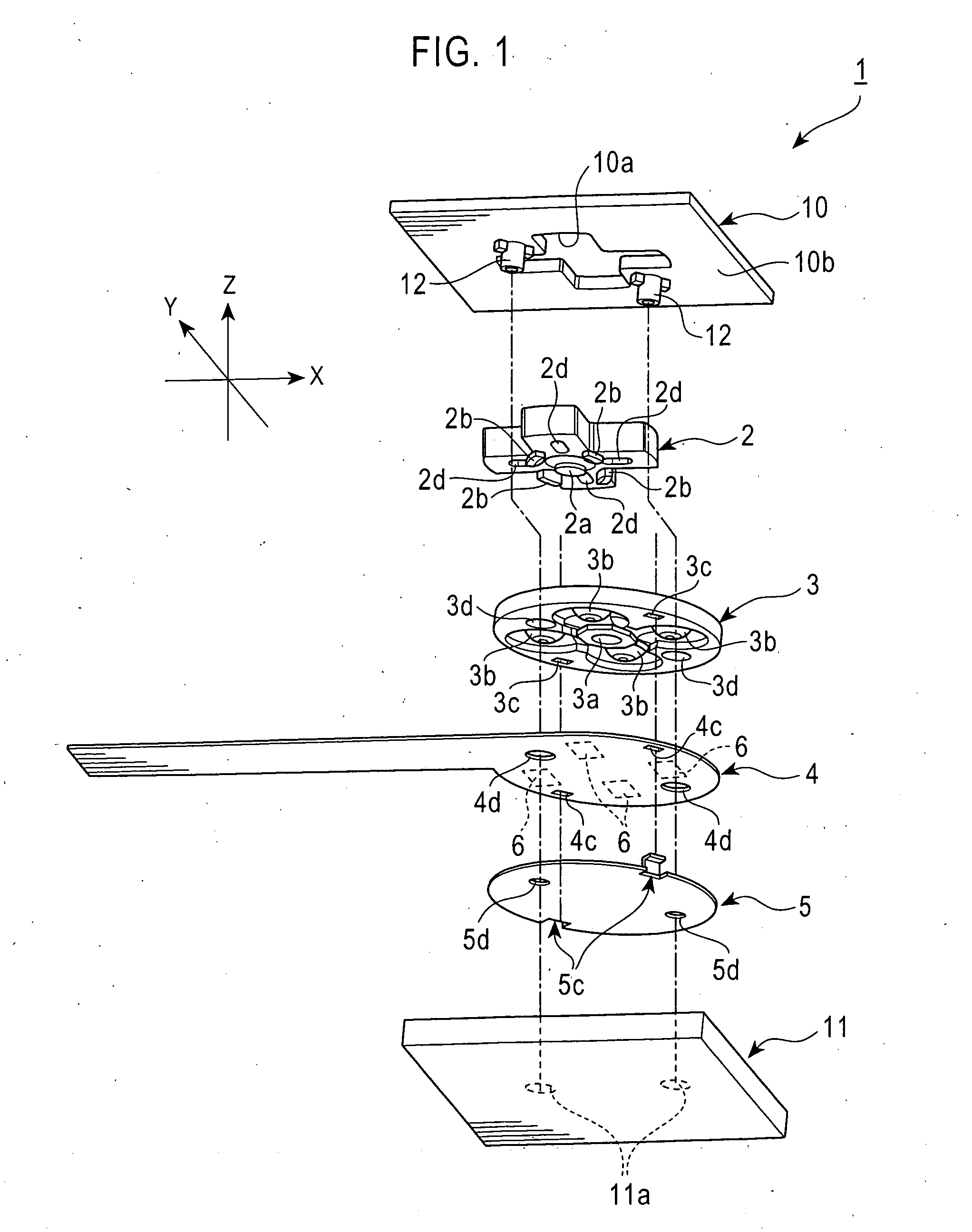
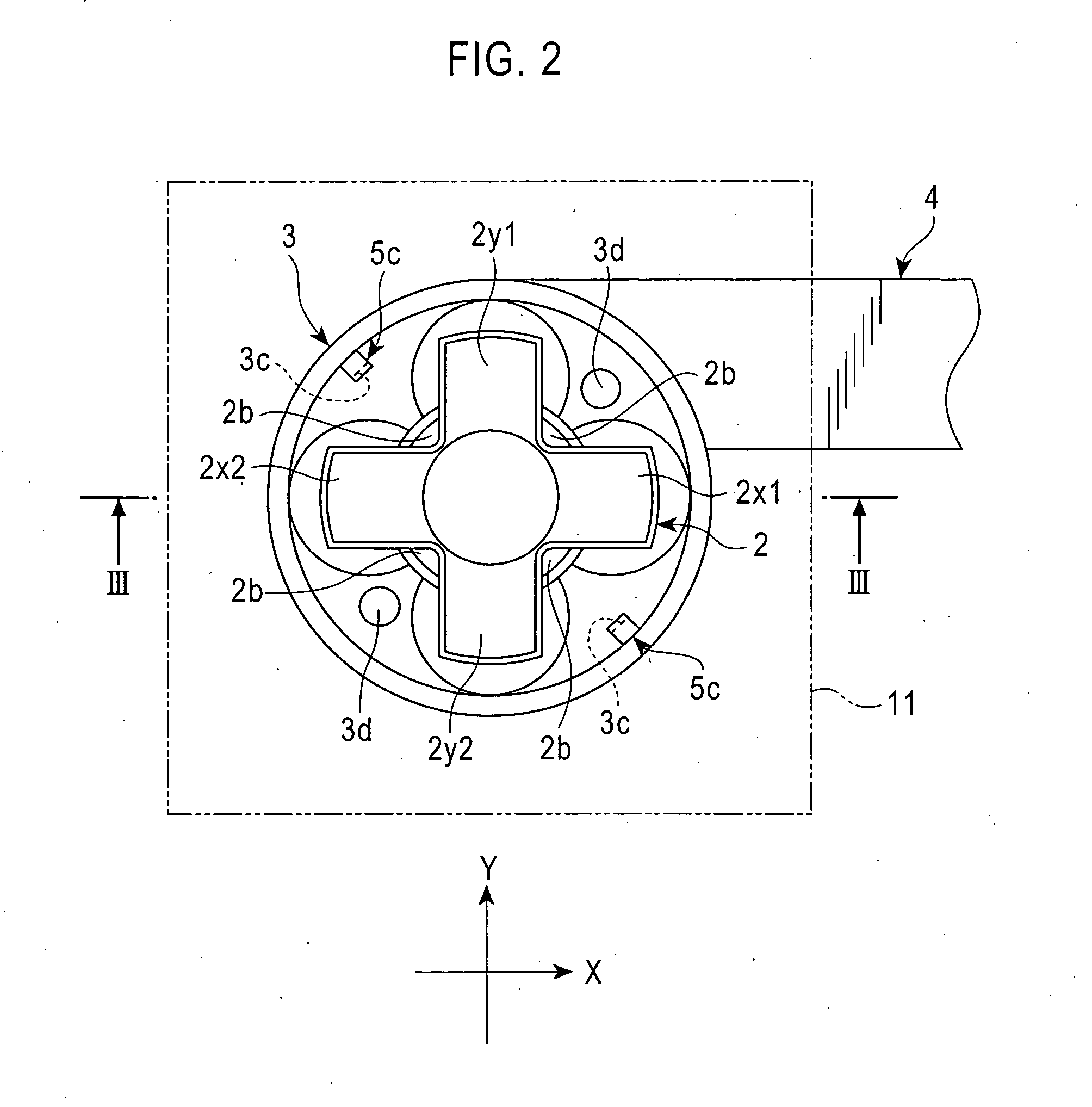
[0024]FIG. 1 is an exploded perspective view of an embodiment of the input device according to the present invention. An input device 1 includes a cross-shaped operating unit 2 composed of synthetic resin or the like and a detecting substrate 4 operated by the operating unit 2. FIG. 2 is a plan view of the input device shown from the operational side. The operating unit 2 has four arms or operating portions 2x1, 2x2, 2y1, and 2y2 extending in four directions. The operating portions operate respective four contacts 6 provided on the detecting substrate 4.

[0025] As shown in FIG. 1, a supporting leg 2a is integrally formed on the operating unit 2 and protrudes from the bottom center of the operating unit 2. An elastic supporting member 3 is provided under the operating unit 2 to support the operating unit 2. The elastic supporting member 3 includes a hole 3a at the center, into which the supporting leg 2a is fitted. Four flanges 2b are integrally formed on the bottom surface of the op...


PUM


Abstract

An input device includes contacts having resistive elements and low-resistance elements opposing the respective resistive elements, an operating unit varying the contact areas between the low-resistance elements and the resistive elements, and detecting means for switching an operation mode of the input device in response to the operation of a supporting leg provided on the operating unit. When the operating unit is not operated, the detecting means switches the operation mode to a sleep mode while the resistive elements and the low-resistance elements are kept in contact with each other. When the operating unit is operated, the detecting means switches the operation mode and the sleep mode is disabled.

Description

BACKGROUND OF THE INVENTION [0001] 1. Field of the Invention [0002] The present invention relates to an input device capable of enabling and disabling a sleep mode, and in particular, relates to an input device whose operability is not impaired when the sleep mode is disabled. [0003] 2. Description of the Related Art [0004] Some input devices for game consoles, personal computers and the like can vary the outputs in an analog fashion in response to the pushing force. [0005] An input device disclosed in Japanese Unexamined Patent Application Publication No. 2002-93274 includes an electrode provided on a substrate and a click rubber member composed of silicone or the like opposing the electrode. Pulsed electricity is supplied to the click rubber member. When a key top is pressed, the click rubber member comes into contact with the electrode to generate an output. When the click rubber member is further pressed to the electrode, the click rubber member is elastically deformed and the o...

Claims


Application Information

Patent Timeline
Patent Type & Authority Applications(United States)
IPC IPC(8): A63F13/24A63F13/493G06F1/32H01H25/00H01H25/04
CPCG06F1/3203G06F1/325G06F3/0338Y02B60/32H01H25/041H01H2239/078H01H2300/022H01H25/008Y02D30/50
Inventor SATO, ISAO
Owner ALPS ALPINE CO LTD
Learn More