Scanner having scan angle multiplier
a scanning angle and multiplier technology, applied in the field of optical scanning apparatuses, can solve the problems of changing the wavelength of light beams, complex transmission optical system, and large number of optical components
- Summary
- Abstract
- Description
- Claims
- Application Information
AI Technical Summary
Benefits of technology
Problems solved by technology
Method used
Image

Examples
first embodiment
<First Embodiment>
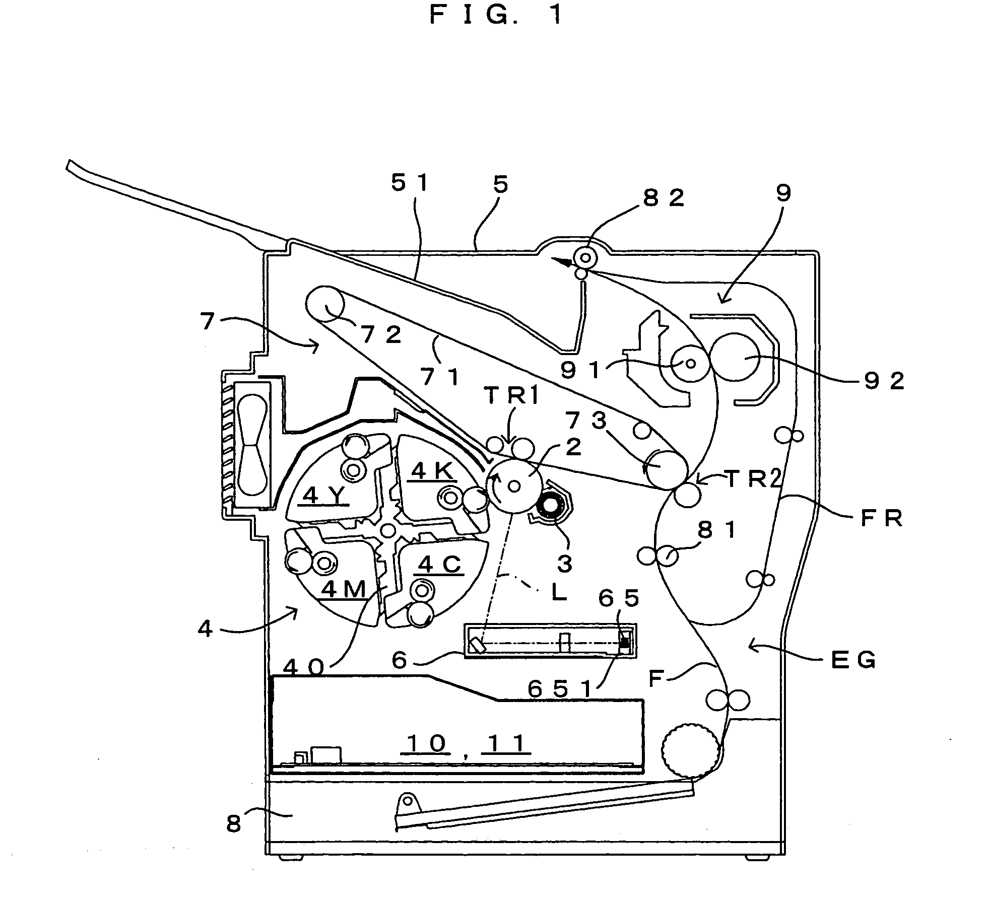
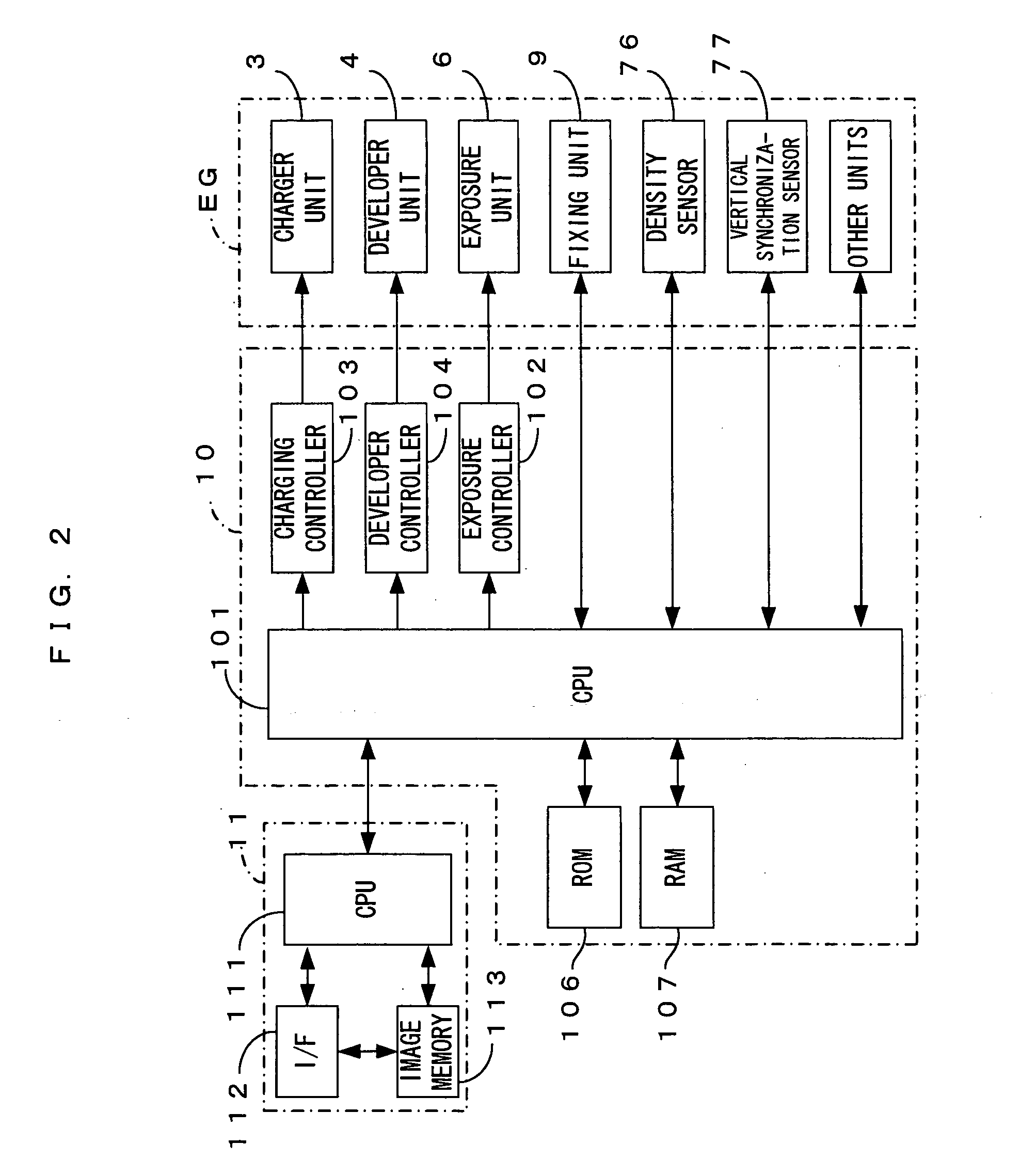
FIG. 1 is a drawing of an image forming apparatus equipped with an exposure unit which is a first embodiment of an optical scanning apparatus according to the present invention. FIG. 2 is a block diagram showing the electric structure of the image forming apparatus which is shown in FIG. 1. This image forming apparatus is a color printer of the so-called 4-cycle method. In this image forming apparatus, when a print command is fed to a main controller 11 from an external apparatus such as a host computer in response to an image formation request from a user, an engine controller 10 controls respective portions of an engine part EG in accordance with the print command from a CPU 111 of the main controller 11, and an image which corresponds to the print command is formed on a sheet which may be a copy paper, a transfer paper, a plain paper or a transparency for an overhead projector.
In the engine part EG, a photosensitive member 2 is disposed so that the photos...
second embodiment
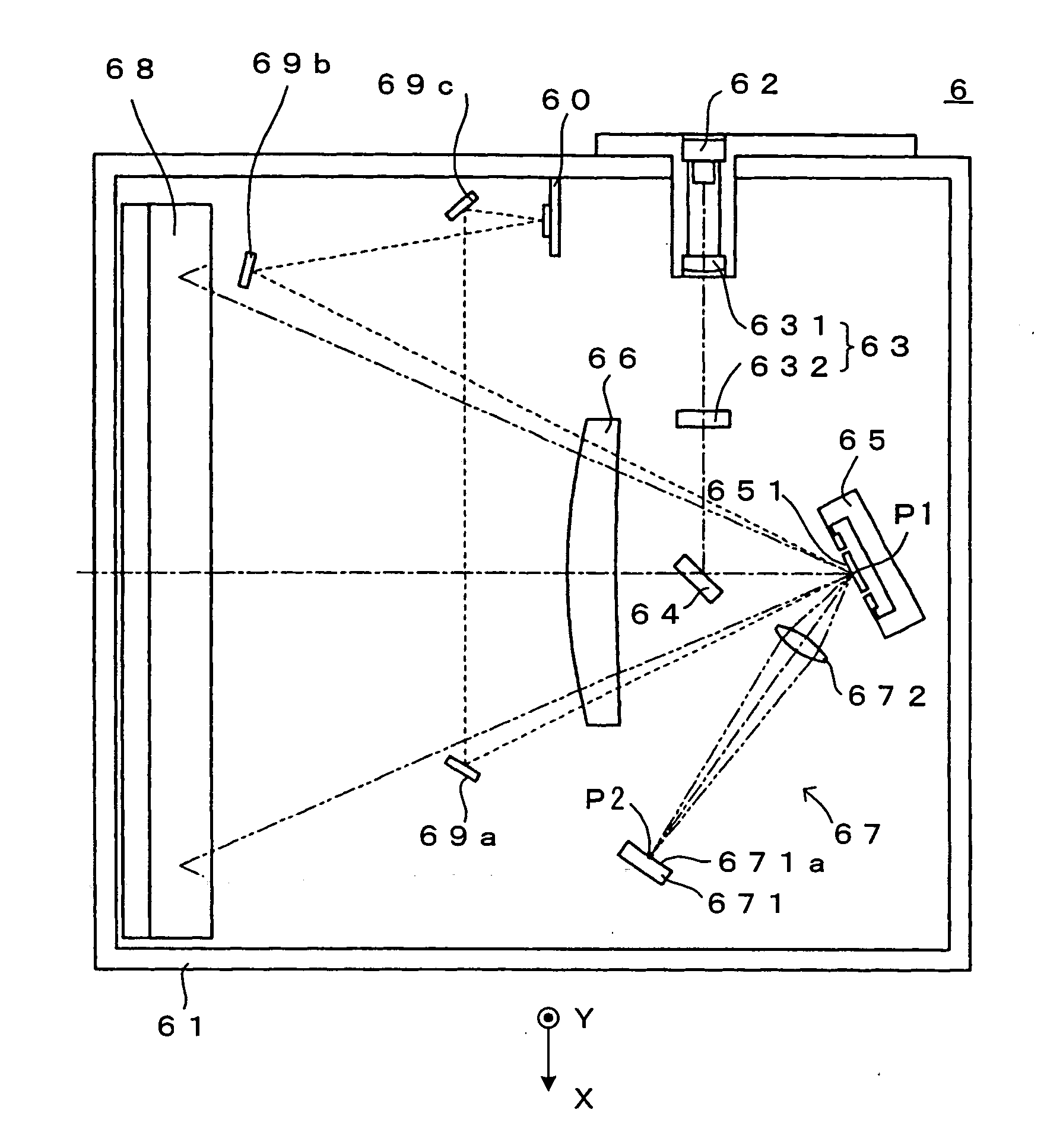
<Second Embodiment>
FIG. 9 is a drawing of a second embodiment of the optical scanning apparatus (exposure unit) according to the present invention. FIG. 10 is a drawing of a transmission optical system which is one of components which form the exposure unit. A major difference of the second embodiment from the first embodiment lies in the structure of the transmission optical system 67, and the other structures are similar to those according to the first embodiment. Hence, the structure and operations of the transmission optical system will be mainly described below.
The transmission optical system 67 comprises a reflection mirror 673 which is disposed with its reflection surface 673a directed toward the deflection mirror surface 651, and two transmission lenses 674 and 675 which are disposed between the reflection mirror 673 and the deflection mirror surface 651. As shown in FIG. 9, the light beam deflected by the deflecting element 65 at the first deflection angle is guided ...
third embodiment
<Third Embodiment>
FIG. 11 is a drawing of a third embodiment of the optical scanning apparatus (exposure unit) according to the present invention. A major difference of the third embodiment from the second embodiment is that as the “two imaging elements” of the present invention, one transmission lens 675 is formed by a spherical lens while the other transmission lens 674 is formed by an aspherical lens. In other words, in this embodiment, the image surface I5 formed by the transmission lens 675 at the intermediate image position P3 is curved as denoted at the broken line in FIG. 11. Therefore, the transmission lens (aspherical lens) 674 is formed so as to exhibit an imaging characteristic which corresponds to the image surface I5. Because of this, the image surfaces I4 and I5 formed by the transmission lenses 674 and 675 approximately coincide with each other at the intermediate image position P3, thereby achieving similar effects to those which are realized by the first embod...
PUM
 Abstract
Description
Claims
Application Information
 - R&D
- Intellectual Property
- Life Sciences
- Materials
- Tech Scout
- Unparalleled Data Quality
- Higher Quality Content
- 60% Fewer Hallucinations
Browse by: Latest US Patents, China's latest patents, Technical Efficacy Thesaurus, Application Domain, Technology Topic, Popular Technical Reports.
© 2025 PatSnap. All rights reserved.Legal|Privacy policy|Modern Slavery Act Transparency Statement|Sitemap|About US| Contact US: help@patsnap.com