Holding member, coolant, cooling method and cooling device, linear motor device, stage device, and exposure apparatus

Inactive Publication Date: 2005-03-17
NIKON CORP
View PDF18 Cites 37 Cited by
  • Summary
  • Abstract
  • Description
  • Claims
  • Application Information

AI Technical Summary

Benefits of technology

[0008] This invention addresses the above-mentioned problems. One object of this invention is to provide a holding member, a coolant, a cooling method, a cooling device, a linear motor device, a stage device, and an exposure apparatus which can substantially reduce and, preferably eliminate, the generation of a temperature difference among at least a part of an object, when cooling an object such as, for example, a coil stored in a housing.

Problems solved by technology

Conventionally, a linear motor is used as a driving source of the substrate stage and mask stage (hereafter both will be referred to as “stage”), but the heat generated by the linear motor affects the positioning of the stages and thus, decreases the accuracy of the stage positions.
For example, the heat generated by a linear motor thermally deforms the surrounding members and devices and also, for example, causes the air temperature to change on an optical path of an optical interference measuring instrument (interferometer) used for detecting a stage position, which causes errors in measurement values.
However, the following problems occur in the above-described conventional linear motor.
Due to this temperature difference, problems arise.
For example, as discussed above, the temperature difference causes air to fluctuate inside a device and thus, reduces the measurement accuracy of an optical interference measuring instrument.

Method used


Image

  • Holding member, coolant, cooling method and cooling device, linear motor device, stage device, and exposure apparatus
  • Holding member, coolant, cooling method and cooling device, linear motor device, stage device, and exposure apparatus
  • Holding member, coolant, cooling method and cooling device, linear motor device, stage device, and exposure apparatus

Examples


first embodiment

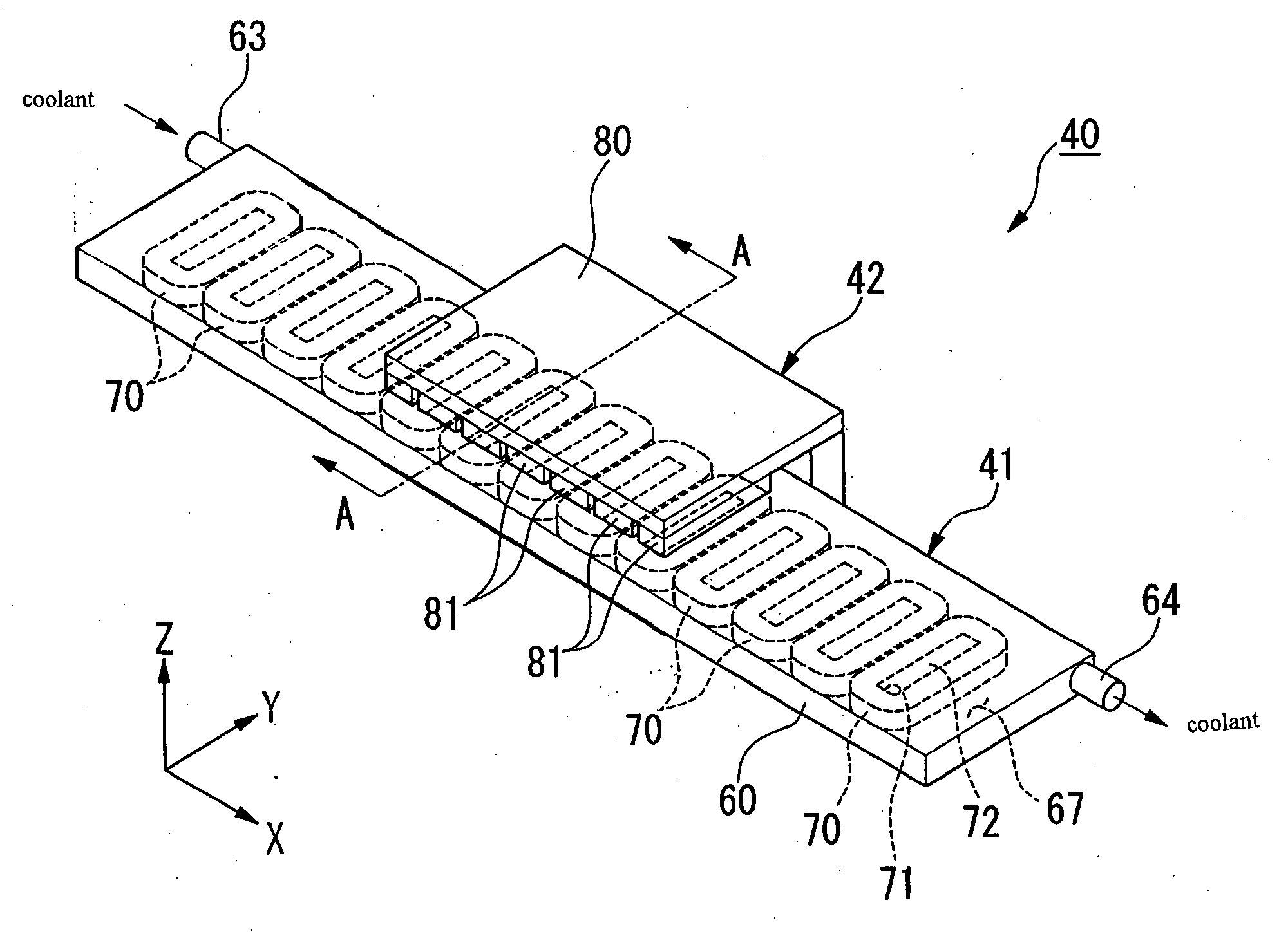
[0067] The following explains linear motors 40 (20, 30) and a cooling system of this invention with reference to FIGS. 4-6. In the following description, the X linear motor 40 arranged in the substrate stage PST is explained, but the linear motors 20 arranged in the Y linear motor 30 and the mask stage MST can have substantially the same structure.

[0068]FIG. 4 is a schematic perspective view of the linear motor (linear motor device) 40.

[0069] As shown in FIG. 4, the linear motor 40 is provided with a stator 41 formed of coil units having the X axis direction (specified direction) as a longitudinal direction thereof, and a movable part 42 formed of magnetic units. The stator 41 has a housing 60 having an internal space 67 and coils 70 arranged in the internal space 67. The coils 70 have central hollow parts 71, and in the central hollow parts 71, supports 72 supporting the coils 70 are arranged. The supports 72 supporting the coils 70 are fixed to the housing 60 by screws (not shown...

second embodiment

[0094] Furthermore, in the second embodiment as well, at least part of the cooling substance (solid substance) which is held in the respective plurality of holding members 200 to be supplied to the internal space 67 from the entrance 63 needs to maintain a solid state without being melted until after it leaves the exit 64. Because of this, the mixing device 92 sets a mixing ratio of the holding members 200 and the liquid within the coolant to be supplied to the internal space 67 at an optimal value in advance. Furthermore, the mixing device 92 sets a mixing ratio of the holding members 200 and the liquid according to the heat amount of the coils 70.

[0095] FIGS. 9(a) and 9(b) are diagrams showing one example of a process of manufacturing the holding members 200. As shown in FIG. 9(a), an injection needle shaped injecting device 202 is inserted to the hollow part 201 of the holding members 200 via a hole 200A. Furthermore, a cooling substance is injected to the hollow part 201 from th...

third embodiment

[0106] FIGS. 11(a) and 11(b) are diagrams showing a holding member. FIG. 11(a) is an outer view, and FIG. 11(b) is a cross-sectional view of FIG. 11(a). The holding members 220 shown in FIGS. 11(a) and 11(b) are formed of a porous body and hold a cooling substance within the porous body. That is, in the holding member 220 shown in FIGS. 11(a) and 11(b) some of the holes among a plurality of porous holes 221 form an internal space for holding a cooling substance. The holding member 220 is formed of a porous material (capable of absorbing liquid like a wick), e.g., sintered metal particles, sintered metal fibers, or the like. When the coils 70 are cooled by using the holding members 220 shown in FIGS. 11(a) and 11(b), in the same manner as in the holding members 210 shown in FIGS. 10(a) and 10(b), first, a cooling substance (liquid substance) which is held in the holding members 220 is solidified by the solidifying device 90. Furthermore, the mixing device 92 mixes holding members 220...


PUM


Abstract

A coolant cools an object (such as, for example, a coil of a linear motor that drives a stage of an exposure apparatus) while suppressing the generation of a temperature distribution in various parts of the object being cooled by using a coolant that includes a first component and a second component dispersed in the first component, the second component increases in temperature by a lesser amount than the first component when a predetermined amount of heat is absorbed by the first and second components, respectively. The second component may be a substance that changes phase (for example, from a solid to a liquid or from a liquid to a gas) in order to absorb the predetermined amount of heat. The second component may have a higher heat capacity than the first component, and may not change phase when it absorbs heat to cool the object.

Description

BACKGROUND OF THE INVENTION [0001] 1. Field of Invention [0002] This invention relates to a holding member, a coolant, a cooling method, a cooling device, a linear motor device, a stage device, and an exposure apparatus. [0003] 2. Description of Related Art [0004] A micro device such as, for example, a semiconductor element, a liquid crystal display element, or the like is manufactured by a photolithography method which transfers a pattern formed on a mask onto a photosensitive substrate. An exposure apparatus used in this photolithography process has a mask stage that supports and two-dimensionally moves a mask and a substrate stage that supports and two-dimensionally moves a substrate, and transfers a pattern formed on the mask onto a substrate via a projection optical system by consecutively moving the mask stage and the substrate stage. Batch type exposure apparatus, which simultaneously transfer an entire pattern of a mask onto a substrate, and scanning type exposure apparatus,...

Claims


Application Information

Patent Timeline
IPC IPC(8): G03F7/20H01L21/027B23Q11/14H02K9/19H02K9/20H02K41/02
CPCG03F7/70758G03F7/70858H02K41/031H02K9/20H02K9/19
Inventor TOTSU, MASAHIROHAZELTON, ANDREW J.REYNOLDS, ED E.BINNARD, MICHAEL B.ARAI, YOICHI
Owner NIKON CORP
Why Eureka
Try Eureka