
Web transfer mechanism for flexible sheet dispenser

Inactive Publication Date: 2005-03-17
GPCP IP HLDG LLC
View PDF34 Cites 2 Cited by
  • Summary
  • Abstract
  • Description
  • Claims
  • Application Information

AI Technical Summary

Benefits of technology

[0015] It is a more specific object of the invention to provide a web sensing mechanism located away from the feed roller, and which avoids substantial double-feed at the time of a web transfer (and consequent excessive waste of web material).
[0017] Another object of the present invention is to provide a web transfer mechanism with simple and intuitive loading / setting characteristics, to thereby permit simple, fool-proof dispenser maintenance by unskilled personnel.

Problems solved by technology

Although economical, the continuous exposure of the soiled toweling is deemed unsightly, and therefore unacceptable to many consumers when compared to many available alternatives.
Further, the exposure and possible reuse of soiled toweling may present additional health hazards and sanitation and hygiene concerns which should be avoided.
Folded towels are, however, not usually the most economical alternative for institutional and other high-volume situations due to the uncontrolled dispensation of toweling.
If a new roll is substituted for a partially depleted or “stub” roll which is thrown away, substantial waste of material can result.
If waste is avoided by letting the stub roll become completely depleted, then the dispenser may sit empty for some time before the roll is replaced, thereby causing inconvenience to users.
ed. Unfortunately, tension responsive transfers are not particularly reliable since conditions other than reaching the end of the roll can trigger their operation, such as the slackening of the web or a break in the web mater
ial. Diameter responsive transfers also have a drawback in that the reserve web begins dispensing prior to the complete exhaustion of the primary
roll. Thus, for at least a short time web material is dispensed simultaneously from both rolls, and again a waste of material re
However, the use of sensing fingers riding on the web material can, depending on the design, produce extra friction which can inadvertently tear the web.
Also, the introduction of additional components to sense the absence of the web and transfer the reserve web into the feed nip between the feed rollers creates additional opportunities for a transfer failure or interference with web feed to occur.
It is evident that interference with the web feed from the reserve roll could result if proper positioning of the transfer device, away from the nip, is not maintained.
While generally quite effective, the movement and spring biasing of a relatively high mass feed roller can lead to difficulties.
If the spring bias is set too high, the biasing force may inhibit smooth feeding of the web material through the rollers, and result in tearing of the web material.
If it is set too low, the mechanism may not actuate effectively to cause a transfer of feed to the reserve roll immediately upon depletion of the stub roll.
Over time, the spring bias provided to move one roll relative to the other is prone to eventually decrease, e.g., due to fatigue of the spring, such that ultimately the spring force may fall below the required relatively narrow range and thus be insufficient to properly actuate a web transfer.
'973 patent and the Jespersen application are not well suited for providing a transfer of web feed in a dispenser with a feed mechanism incorporating an automatic cutting knife within the main feed roller.
Use of a web sensor positioned against or near a feed roller having an integral web cutting knife, as taught in the '461 patent, would be problematic due to the emergence of the cutting knife as the feed roll rotates.

Method used


Image

  • Web transfer mechanism for flexible sheet dispenser
  • Web transfer mechanism for flexible sheet dispenser
  • Web transfer mechanism for flexible sheet dispenser

Examples


Embodiment Construction

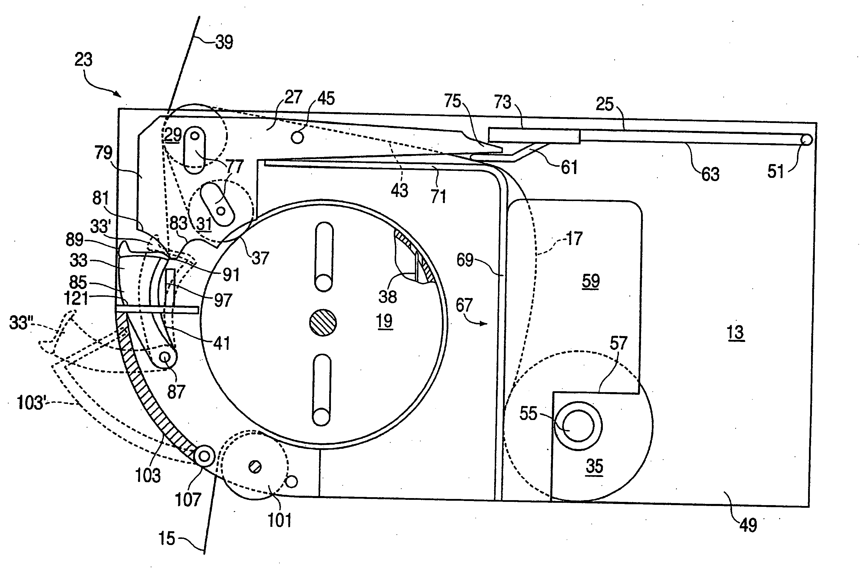
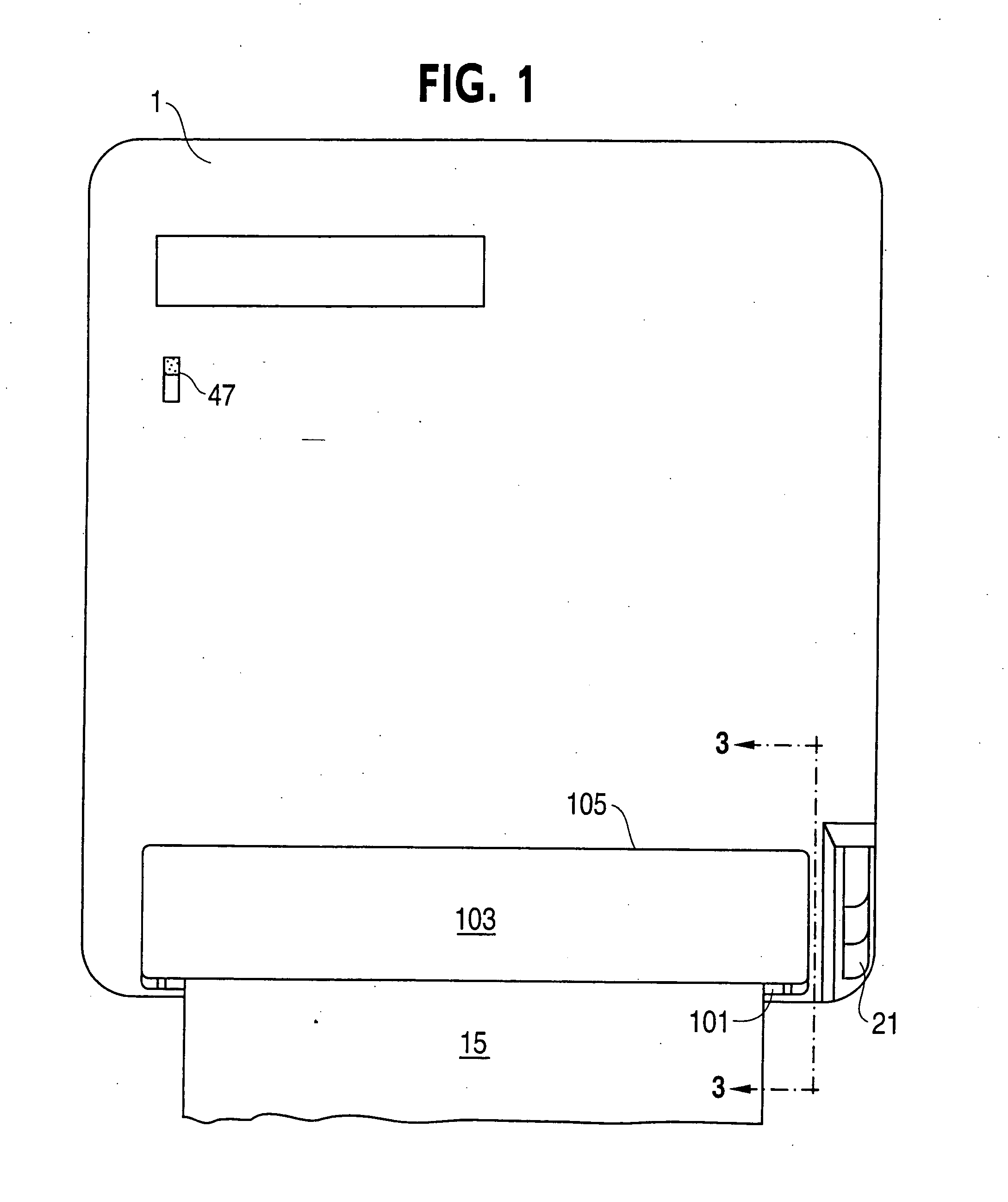
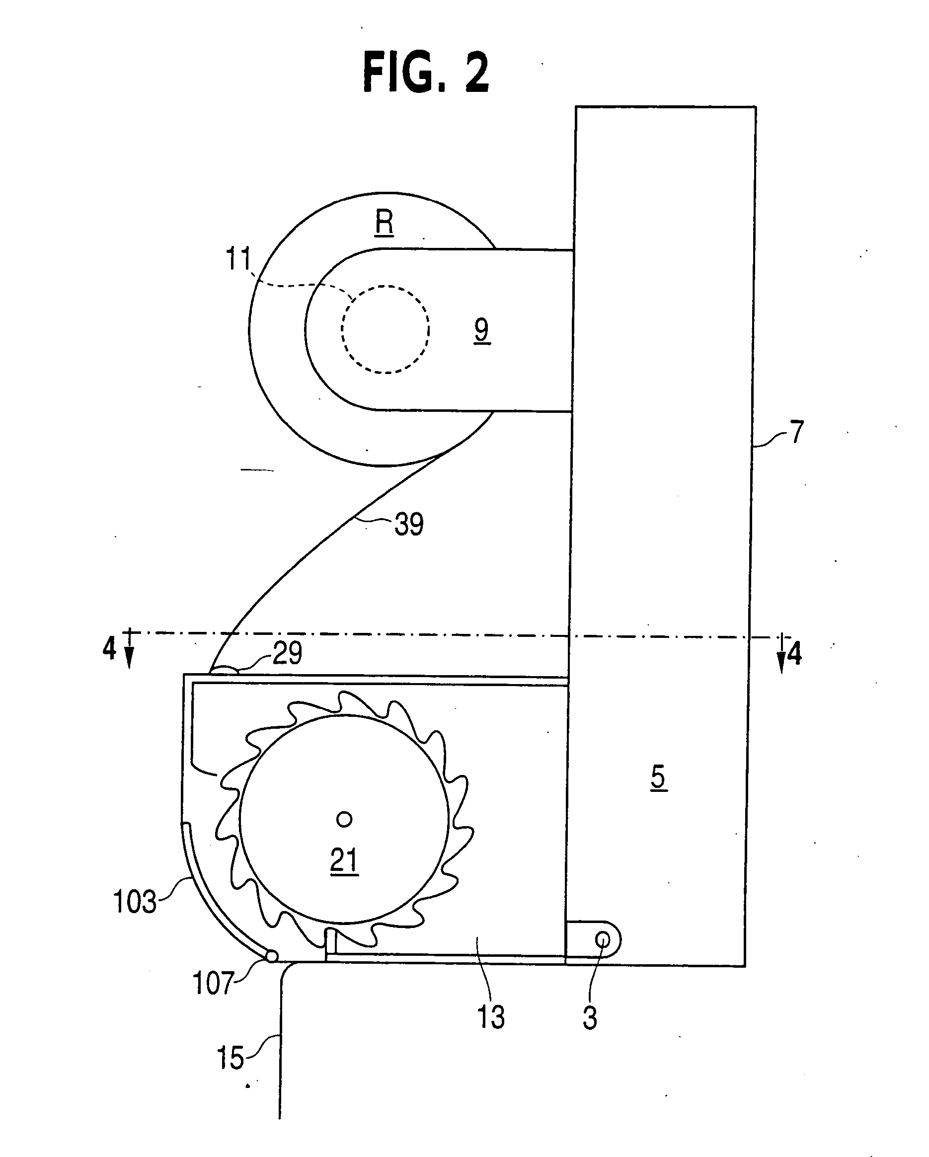
[0030] Referring to FIGS. 1 and 2, it is seen that a dispenser in accordance with the present invention may employ a generally conventional-style exterior dispenser cabinet, e.g., the type used in the commercially available Georgia-Pacific P-12 dispenser. The cabinet shown includes a five-sided cover 1 that is pivotally mounted, at a pivot point 3 (see FIG. 2), to a relatively shallow tray-like base member 5. Base member 5 has a back wall 7 with appropriate openings (not shown) to accommodate fasteners for attachment of the dispenser to a wall.

[0031] A reserve roll R of flexible sheet material, such as paper toweling, may be suitably supported between a pair of cantilever mounted wing members 9 extending from the inside surface of back wall 7. Each wing member carries a cup 11 at its free end, which enters into the opposite ends of the core of reserve roll R. The mounting of reserve roll R within the dispenser housing is conventional, and thus no further discussion of this structur...


PUM

PropertyMeasurementUnit
Flexibilityaaaaaaaaaa
Proximity effectaaaaaaaaaa

Abstract

An automatic web transfer mechanism in a flexible sheet material dispenser includes a web-sensing member operatively coupled with a transfer arm. The member senses the absence of web from a stub roll at a pre-feed portion between the stub roll and a feed roll nip to activate a transfer of feed to the web of a reserve roll. The transfer is initiated by a transfer arm that advances the reserve web into the proximity of the feed roller nip. In a second aspect, a movable front shield opens automatically upon opening of the outer dispenser cover, presenting an opening for pre-transfer placement and retention of a leading edge of web material from the reserve roll. Upon closure of the dispenser cover, the front shield returns to a closed position placing the transfer arm in a pre-transfer set position.

Description

BACKGROUND OF THE INVENTION [0001] This application is a divisional application of U.S. application Ser. No. 09 / 435,718, filed Nov. 8, 1999. [0002] The present invention relates to flexible sheet dispensers for sequentially dispensing a web of material from a plurality of rolls, and in particular to an automatic transfer mechanism for transferring the feed supply from a working roll to a reserve roll, upon exhaustion of the working roll. [0003] Dispensers for toweling are primarily designed to dispense either a continuous length of web material, folded paper towels, or rolls of paper towels. Continuous towels are generally made of a reusable material and form a towel loop outside of the dispenser cabinet for the consumer to use. Folded towels are paper towels which are pre-cut and folded into various configurations to be individually dispensed for use. Roll towels are continuous rolls of paper toweling which are typically wound around a cardboard core and which are, upon dispensing,...

Claims


Application Information

Patent Timeline
IPC IPC(8): A47K10/36
CPCA47K10/3687A47K10/36A47K10/3643A47K2010/365A47K2010/3681Y10T83/4804Y10T83/896Y10T83/4818
Inventor RASMUSSEN, HOLGER
Owner GPCP IP HLDG LLC
Learn More