Constant differential pressure valve

a constant differential pressure valve and valve body technology, applied in the direction of fluid pressure control, lighting and heating apparatus, instruments, etc., can solve the problems of increasing the manufacturing cost of the increasing the size of the entire constant differential pressure valve, etc., and achieve the effect of compact size and low cos

Inactive Publication Date: 2005-03-17
TGK
View PDF5 Cites 17 Cited by
  • Summary
  • Abstract
  • Description
  • Claims
  • Application Information

AI Technical Summary

Benefits of technology

The present invention has been made in view of these points, and an object thereof is to provide a constant differential pressure valve which is compact in size and realized at low cost.

Problems solved by technology

However, this arrangement causes an increase in the size of the entire constant differential pressure valve because the body block is formed separately from the piping of the refrigeration cycle, and further, an internal refrigerant passage where internal structures of the differential pressure control mechanism, such as the valve element, are arranged, and a solenoid section for drivingly controlling the internal structures are disposed in the body block separately from each other.
Further, it is necessary to perform complicated adjustment for arranging respective pipes of refrigerant inlet and outlet passages and the internal refrigerant passage connecting the pipes, according to the construction of the differential pressure control mechanism within the body block, which causes an increase in the manufacturing costs of the constant differential pressure valve.

Method used


Image

  • Constant differential pressure valve
  • Constant differential pressure valve
  • Constant differential pressure valve

Examples


Embodiment Construction

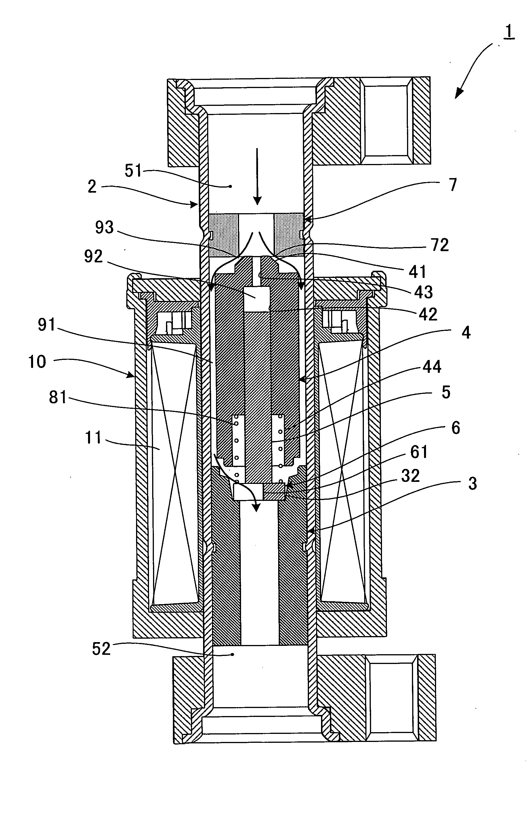
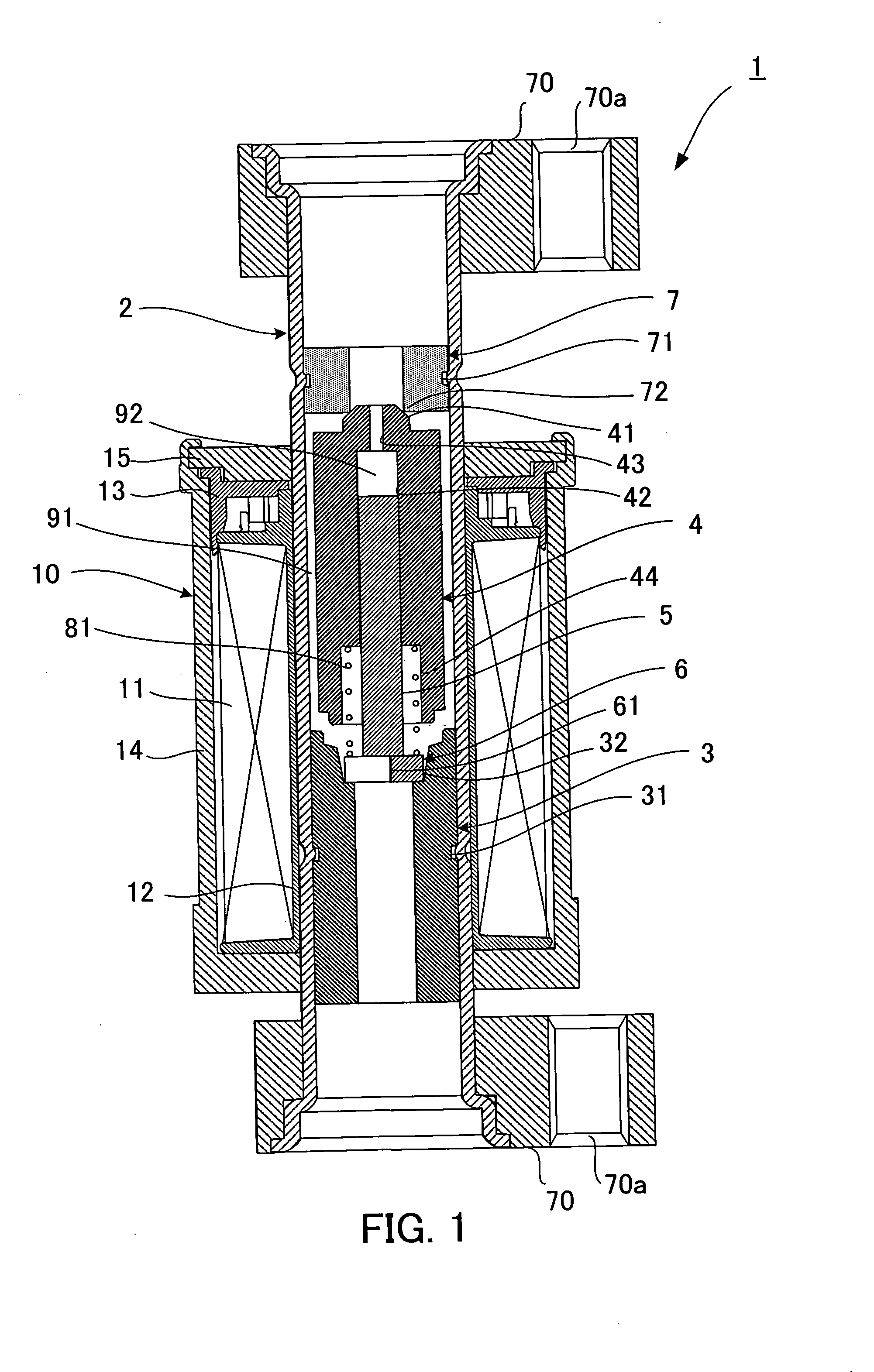
Hereinafter, an embodiment of the present invention will be described in detail with reference to the drawings. FIG. 1 is a cross-sectional view of a constant differential pressure valve of the present embodiment. In the following description, an upper side and a lower side as viewed in the figure will be also referred to as the upstream side and the downstream side, respectively, with reference to the direction of flow of refrigerant.

As shown in FIG. 1, the constant differential pressure valve 1 is comprised of a body formed by a pipe 2 in the form of a hollow cylinder which both ends are opening, a fixed core 3, a movable core 4, a solid shaft 5, a stopper 6, and a hollow cylindrical member 7, accommodated in the pipe 2, and a solenoid section 10 disposed on the outer periphery of the pipe 2 in a manner surrounding the same.

Piping joints 70 having a generally oval shape are attached to respective both ends of the pipe 2. Each of the ends of the pipe 2 has its diameter increas...


PUM


Abstract

To provide a constant differential pressure valve which is compact in size and can be realized at low cost. In the constant differential pressure valve according to the present invention, a pipe forming a body thereof not only accommodates internal structures, such as a differential pressure control mechanism, a movable core, and a fixed core, but also serves as part of piping of a refrigeration cycle. Further, a solenoid section including a solenoid coil is disposed outside the pipe in a manner surrounding the same. Therefore, substantial integration of the differential pressure control mechanism into the piping of the refrigeration cycle can be achieved, which makes the entire constant differential pressure valve very simple in construction. As a result, reduction of the size of the constant differential pressure valve and resultant reduction of material costs and manufacturing costs can be achieved, which makes it possible to achieve low costs of the constant differential pressure valve.

Description

CROSS-REFERENCES TO RELATED APPLICATIONS, IF ANY This application claims priority of Japanese Patent Application No. 2003-320508 filed on Sep. 12, 2003, entitled “CONSTANT DIFFERENTIAL PRESSURE VALVE”. BACKGROUND OF THE INVENTION (1) Field of the Invention The present invention relates to a constant differential pressure valve disposed in a passage of refrigerant circulating through a refrigeration cycle, for controlling the flow rate of the refrigerant according to the amount of an electric current supplied to the valve, such that a differential pressure of the refrigerant across the valve is held constant. (2) Description of the Related Art Conventionally, in a refrigeration cycle e.g. for an automotive air conditioner, a high-temperature, high-pressure gaseous refrigerant compressed by a compressor is condensed or cooled by a condenser or a gas cooler, and then the condensed or cooled refrigerant is changed into a low-temperature, low-pressure refrigerant by a decompression ...

Claims


Application Information

Patent Timeline
Patent Type & Authority Applications(United States)
IPC IPC(8): F16K31/06F25B41/06G05D16/20
CPCF16K31/0651F16K31/0655F25B41/062G05D16/2013F25B2600/2505Y02B30/72F25B2341/065G05D16/028G05D16/2022Y02B30/70F25B41/34F25B41/345
Inventor HIROTA, HISATOSHI
Owner TGK
Why Eureka
Try Eureka