
Insulated stud panel and method of making such

a technology of insulated studs and studs, which is applied in the field of stud panels, can solve the problems of consuming a great amount of time, reducing the r-value, and reducing the acceptance of standard products, so as to reduce the empty space, reduce the r-value, and reduce the effect of foam density

Inactive Publication Date: 2005-03-17
HAGEN HANS T JR +1
View PDF45 Cites 112 Cited by
  • Summary
  • Abstract
  • Description
  • Claims
  • Application Information

AI Technical Summary

Benefits of technology

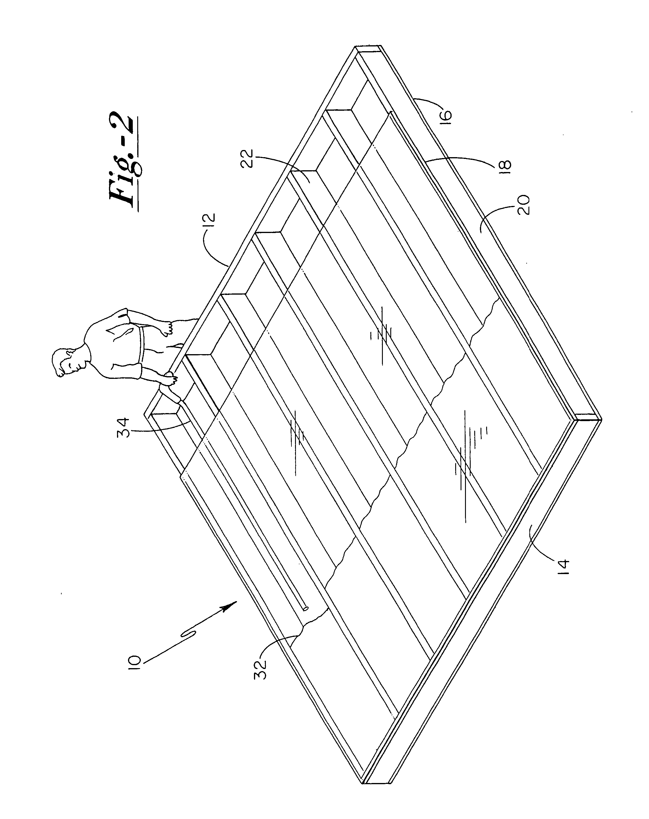
[0007] Another feature of the present invention is the provision in such a method, of the step of permitting the interior sheathing to be removable from the stud panel without damaging the integrity of the interior sheathing or stud panel as a whole such that the removable interior sheathing may be a rigid panel of transparent plastic temporarily fixed in place or laying on top of a remainder of the stud panel.
[0030] Another advantage of the present invention is that air will not pass through small holes in sheathing when fasteners, air duct or openings are inserted through sheathing.

Problems solved by technology

One problem relates to scarfing.
Scarfing is an undesirable job in the housing industry because it consumes a great amount of time, provides merely a rough or coarse trim, wastes insulation, requires the user to find land fills that accept insulation waste, and then requires the user to actually transport the waste material to such land fills.
Another problem is the acceptance of standard uses for standard products.
Whereas an efficient culture may find a use for each and every part of each and every animal that is killed, an inefficient culture may dispose of a great portion of the same animal.
Another problem is a poorly insulated exterior wall.

Method used


Image

  • Insulated stud panel and method of making such
  • Insulated stud panel and method of making such
  • Insulated stud panel and method of making such

Examples


Embodiment Construction

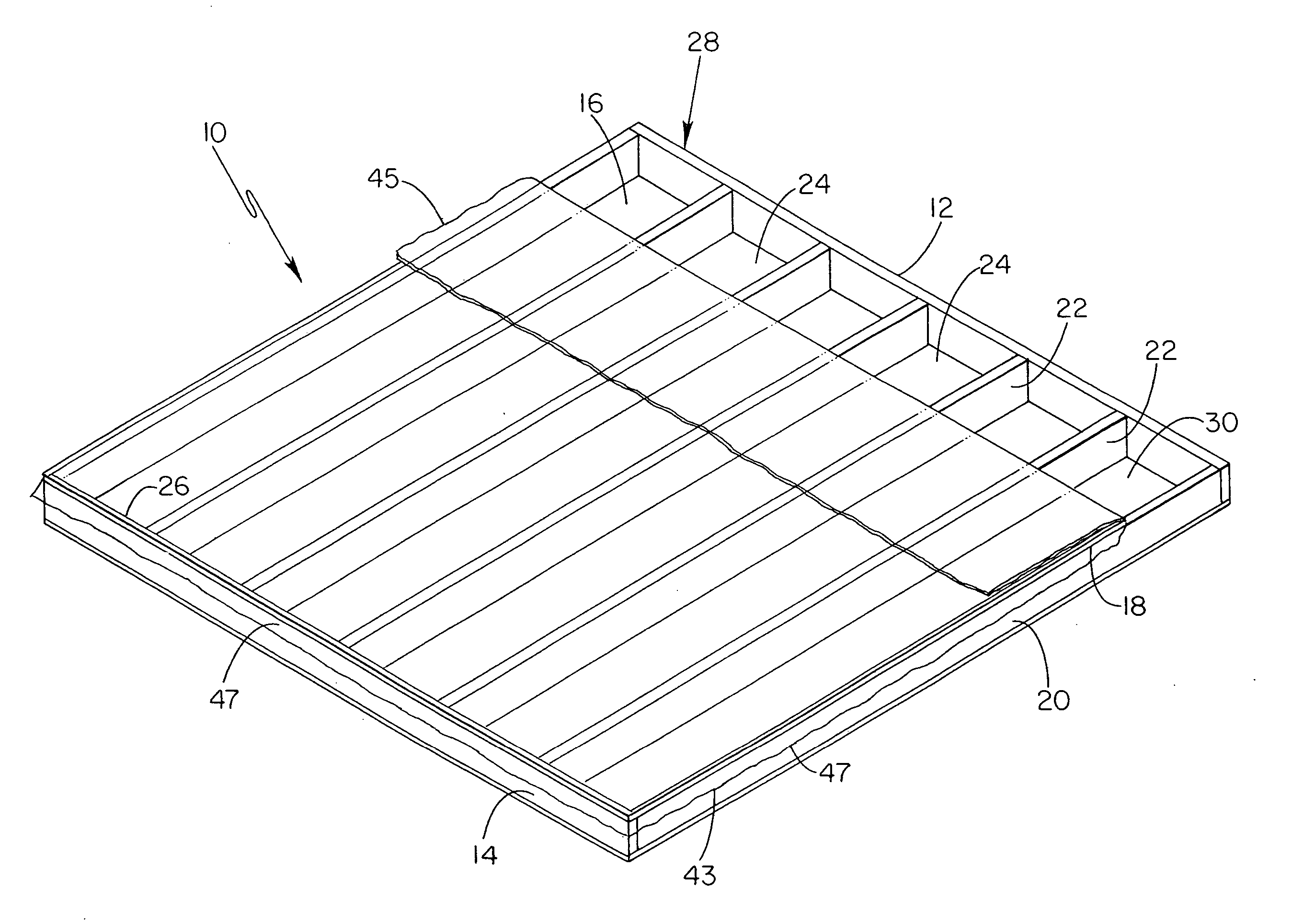
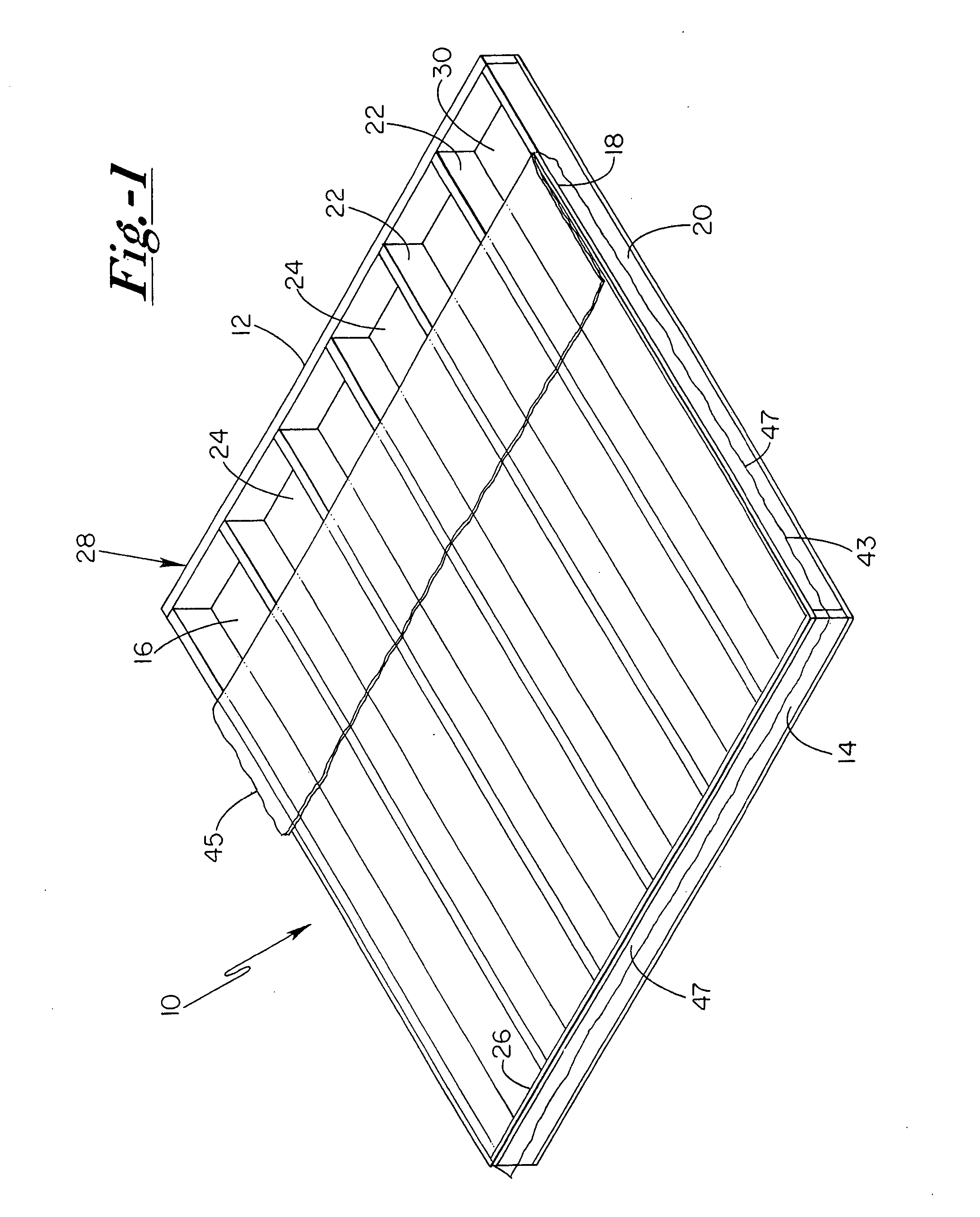
[0057]FIG. 1 shows a stud panel 10 of the present invention. Stud panel 10 includes a first, top (or bottom) plate 12, a second, bottom (or top) plate 14, exterior (or interior) sheathing 16, interior (or exterior) sheathing 18, a pair of end or outer studs 20, and a set of interior or inner studs 22, where studs 20 and 22 are between the first and second plates 12, 14 and further between the exterior and interior sheathing 16, 18. The stud panel 10 includes a set of inner regions or spaces 24, where each of the inner regions 24 is defined by inner faces of the first and second plate 12, 14, inner faces of the exterior and interior sheathing 16, 18, and inner faces of adjacent studs, where such adjacent studs are a combination of an outer stud and inner stud or a combination of two inner studs. Each of the inner regions 24, in the panel of FIG. 1, includes a closed end 26, into which insulation can be first introduced, and an open end 28, into which insulation can be introduced as a...


PUM

PropertyMeasurementUnit
Densityaaaaaaaaaa
Lengthaaaaaaaaaa
Coloraaaaaaaaaa

Abstract

A stud panel and method of making a stud panel where interior sheathing may be a temporary piece of transparent plastic or a permanent panel of sheet rock so as to retain insulation in place and minimize scarfing. The stud panel may include studs having through holes extending in a length direction of the stud panel such that insulation in adjacent inner regions separated by such studs interlock with each other and contribute to a structural integrity of the stud panel. The stud panel may include a space between inner studs and one of the exterior and interior sheathing so as to provide a thermal and sound break between the exterior and inner sheathing so as to minimize heat, air and sound transfer between the exterior and interior sheathing. A method of making the stud panel is further disclosed, where such a method may include the step of incrementally introducing insulation from a closed end of an inner region to an open end of an inner region and may further include the step of automatically introducing insulation into the inner regions of the stud panel.

Description

[0001] This application claims the benefit under 35 U.S.C. 119(e) of U.S. Provisional Patent Application No. 60 / 476,774 filed Jun. 6, 2003. Such provisional application is hereby incorporated by reference in its entirety into this application.FIELD OF THE INVENTION [0002] The present invention relates generally to a stud panel, more particularly to an insulated stud panel, and specifically to a prefabricated insulated stud panel. BACKGROUND OF THE INVENTION [0003] Features of the present invention provide solutions to a number of problems now found in the housing industry. One problem relates to scarfing. “To scarf” means to trim or to cut off excess material. Scarfing, in the housing industry, means to trim or cut off insulation which protrudes from or has expanded outside of desired areas. Scarfing is an undesirable job in the housing industry because it consumes a great amount of time, provides merely a rough or coarse trim, wastes insulation, requires the user to find land fills...

Claims


Application Information

Patent Timeline
IPC IPC(8): E04B1/74E04B1/76E04B2/70E04C2/296
CPCE04B1/7604E04C2/386E04B2001/743E04B2/707B29C44/18B29C44/60Y02A30/244
Inventor HAGEN, HANS T. JR.LESLIE, ROBERT H.DEMERS, ROBERT A.
Owner HAGEN HANS T JR
Learn More