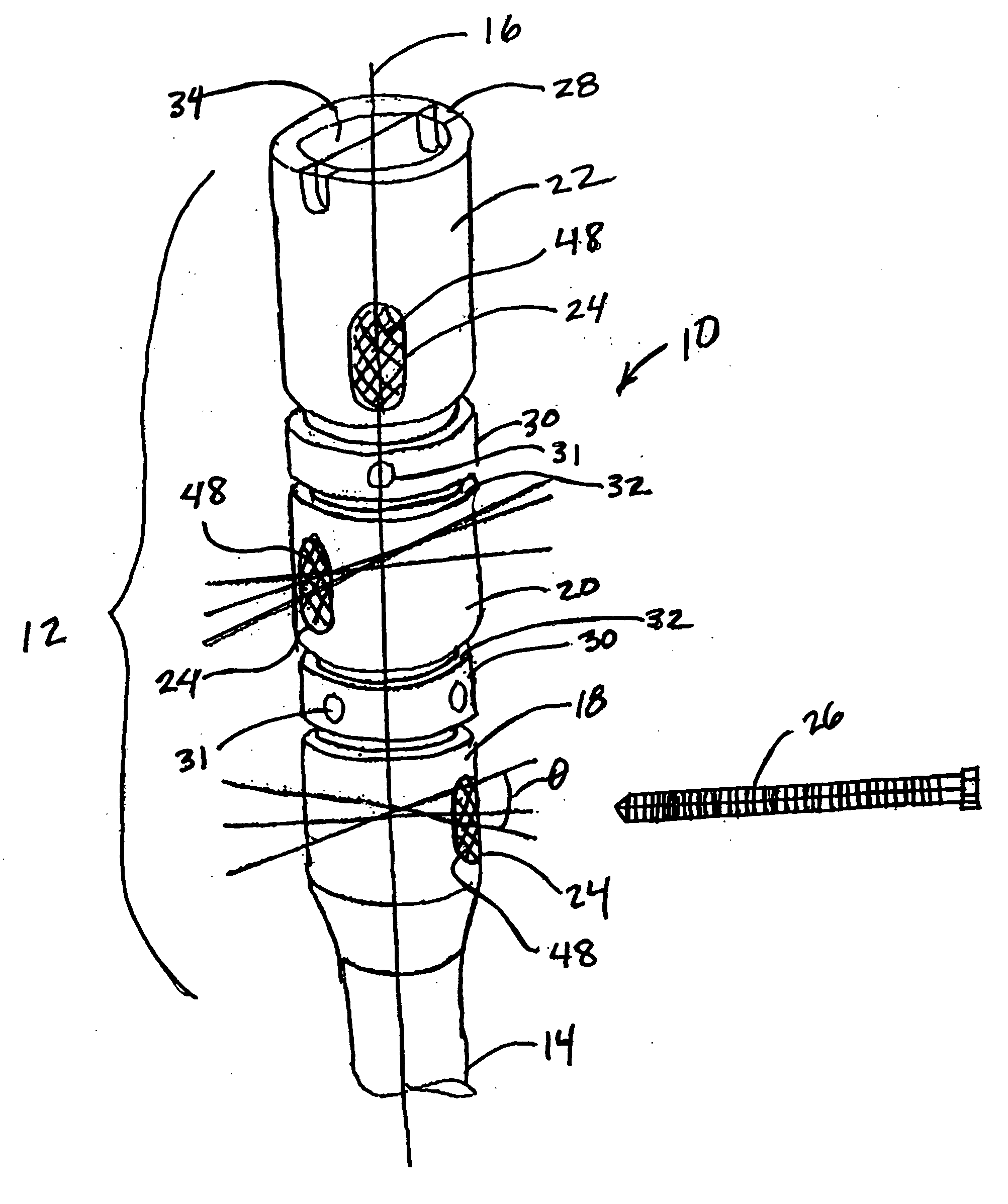
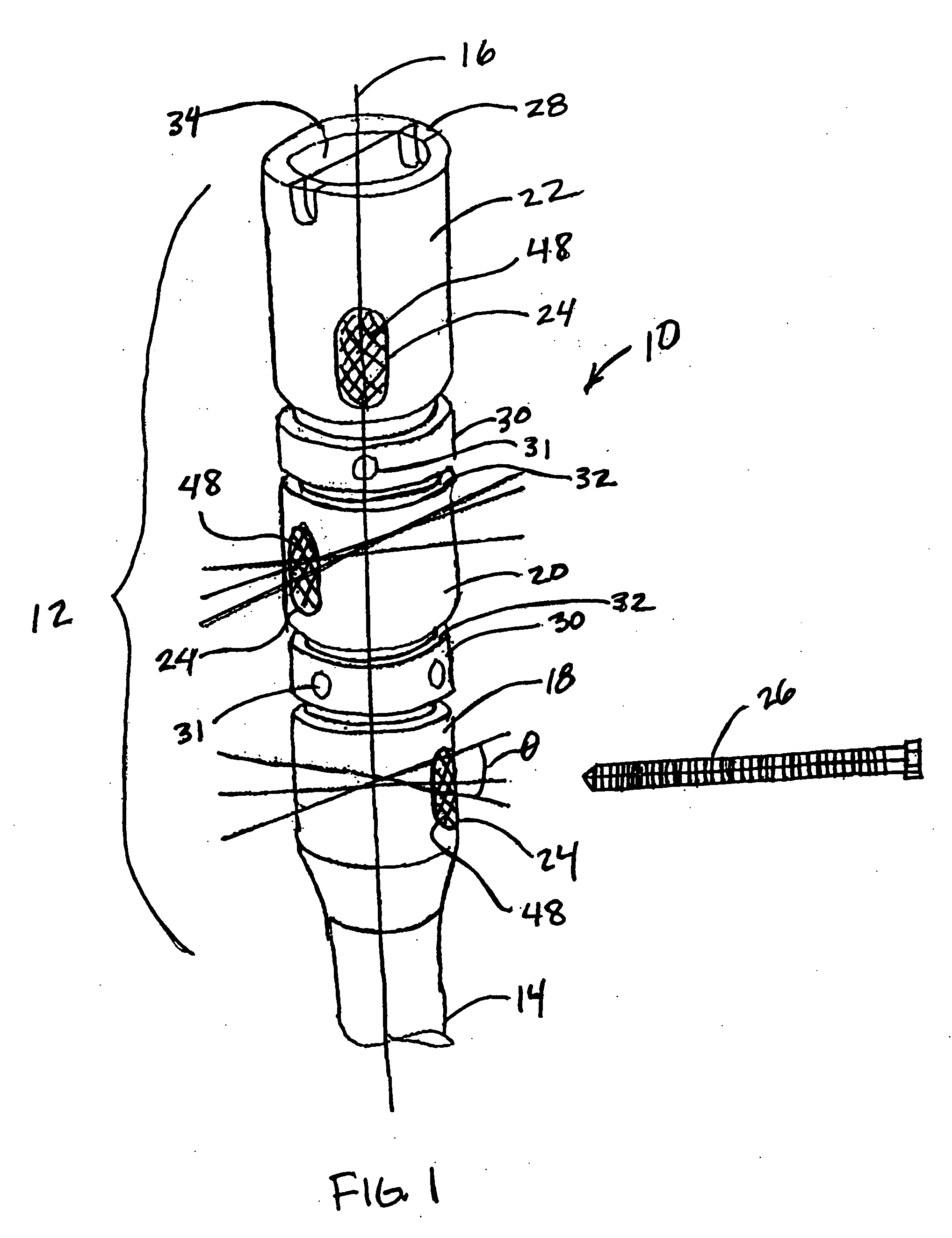
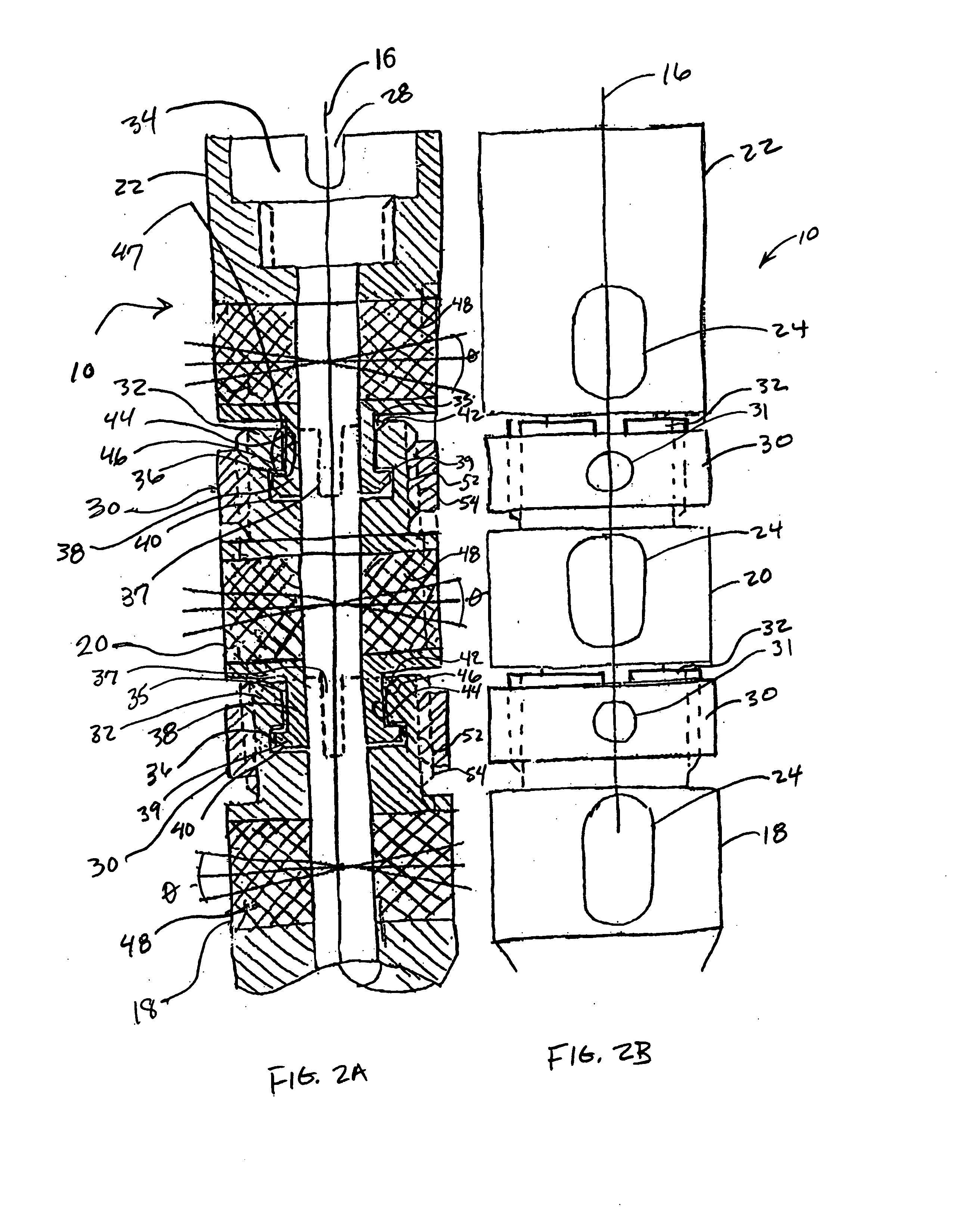
Intramedullary nail for long bone fractures
a technology for fractured bone fragments and intramedullary nails, which is applied in the field of adjustable nails, can solve the problems of increased and unnecessary inventory, increased hospital and patient costs, and difficulty in providing a nail with receiving openings that are properly positioned to enable the treatment of fractured bone fragments. , to achieve the effect of simple design and manufacturing
- Summary
- Abstract
- Description
- Claims
- Application Information
AI Technical Summary
Benefits of technology
Problems solved by technology
Method used
Image
Examples
second embodiment
[0052] Reference will now to made to FIGS. 3A and 3B to describe the present invention. As previously discussed, the embodiments of the invention illustrated herein are merely exemplary of the possible embodiments of the invention, including that illustrated in FIGS. 3A and 3B.
[0053] It will be appreciated that the second embodiment of the invention illustrated in FIGS. 3A and 3B contains many of the same structures represented in FIGS. 1-2, and the new or different structures will be explained to most succinctly explain the additional advantages which come with the embodiments of the invention illustrated in FIGS. 3A and 3B.
[0054] The second embodiment of the intramedullary nail 10a may include a projection 56 on an exterior surface of the connector 38, and a groove 58 may be provided on the interior surface of the sidewall 32 to further provide an interference fit between the sidewall 32 and the connector 38. It will also be appreciated that the projection 56 may be provided on t...
third embodiment
[0057] Reference will now to made to FIGS. 4A-4B to describe the present invention. As previously discussed, the presently disclosed embodiments of the invention illustrated herein are merely exemplary of the possible embodiments of the invention, including that illustrated in FIGS. 4A-4B.
[0058] It will be appreciated that the third embodiment of the invention illustrated in FIGS. 4A-4B contains many of the same structures represented in FIGS. 1-3 and only the new or different structures will be explained to most succinctly explain the additional advantages which come with the embodiments of the invention illustrated in FIGS. 4A-4B. The third embodiment of the intramedullary nail 10b may include the locking ring 30b without threads. The locking ring 30b may include a tapered interior surface 62 that corresponds with a tapered exterior surface 64 of the sidewall 32. The locking ring 30b may also include one or more tool slots 66 for inserting a tool such as a screw driver or other fo...
fourth embodiment
[0060] Reference will now to made to FIGS. 5A-7B to describe the present invention. As previously discussed, the embodiments of the invention illustrated herein are merely exemplary of the possible embodiments of the invention, including that illustrated in FIGS. 5A-7B.
[0061] It will be appreciated that the fourth embodiment of the invention illustrated in FIGS. 5A-7B contains many of the same structures represented in FIGS. 1-4 and only the new or different structures will be explained to most succinctly explain the additional advantages which come with the embodiments of the invention illustrated in FIGS. 5A-7B. The fourth embodiment intramedullary nail 10c may include a recess 68 formed on the connector 38. The recess 68 may extend around the perimeter of the connector 38. Also, a pin 70 may be received in a support 72, such as a transverse through-bore in the sidewalls 32. It will be appreciated that a plurality of supports 72 may be provided for receiving pins 70 for use with a...
PUM
 Abstract
Description
Claims
Application Information
 - R&D
- Intellectual Property
- Life Sciences
- Materials
- Tech Scout
- Unparalleled Data Quality
- Higher Quality Content
- 60% Fewer Hallucinations
Browse by: Latest US Patents, China's latest patents, Technical Efficacy Thesaurus, Application Domain, Technology Topic, Popular Technical Reports.
© 2025 PatSnap. All rights reserved.Legal|Privacy policy|Modern Slavery Act Transparency Statement|Sitemap|About US| Contact US: help@patsnap.com


