
Method for monitoring plasma processing apparatus

Inactive Publication Date: 2005-03-10
SASAKI ICHIRO +3
View PDF5 Cites 24 Cited by
  • Summary
  • Abstract
  • Description
  • Claims
  • Application Information

AI Technical Summary

Benefits of technology

[0013] The present invention comprises a vacuum process chamber that contains an upper electrode having a conductive plate with gas supply holes for supplying a process gas and a lower electrode having a platform on which a sample is to be mounted; process gas supply means for supplying the process gas to the gas supply holes in the upper electrode and exhaust means for exhausting the vacuum process chamber; a high frequency power supply for apply

Problems solved by technology

Such a larger gap or holes may result in another plasma occurring in the defined space.
If the abnormal discharge occurs, a dissociation state of the process gas changes to deteriorate the etching capability thereof, or a reaction product film formed in the reactor is peeled off creating a foreign matter.
Therefore, if components are worn and deteriorated causing abnormal discharge to occur, a normal etching can no longer be accomplished.
However, abnormal discharge sometimes occurs before the elapse of reference time for component replacement.
Thus, by that time, a considerable amount of poorly processed wafers would have resulted.
Besides, according to the method described in the Japanese Patent Laid-Open No. 9-92491 described above, while the abnormal discharge occurring in the plasma can be detected, any abnormal discharge occurring with the inner portion of the gas hole of the upper electrode as described above cannot be detected.

Method used


Image

  • Method for monitoring plasma processing apparatus
  • Method for monitoring plasma processing apparatus
  • Method for monitoring plasma processing apparatus

Examples


Embodiment Construction

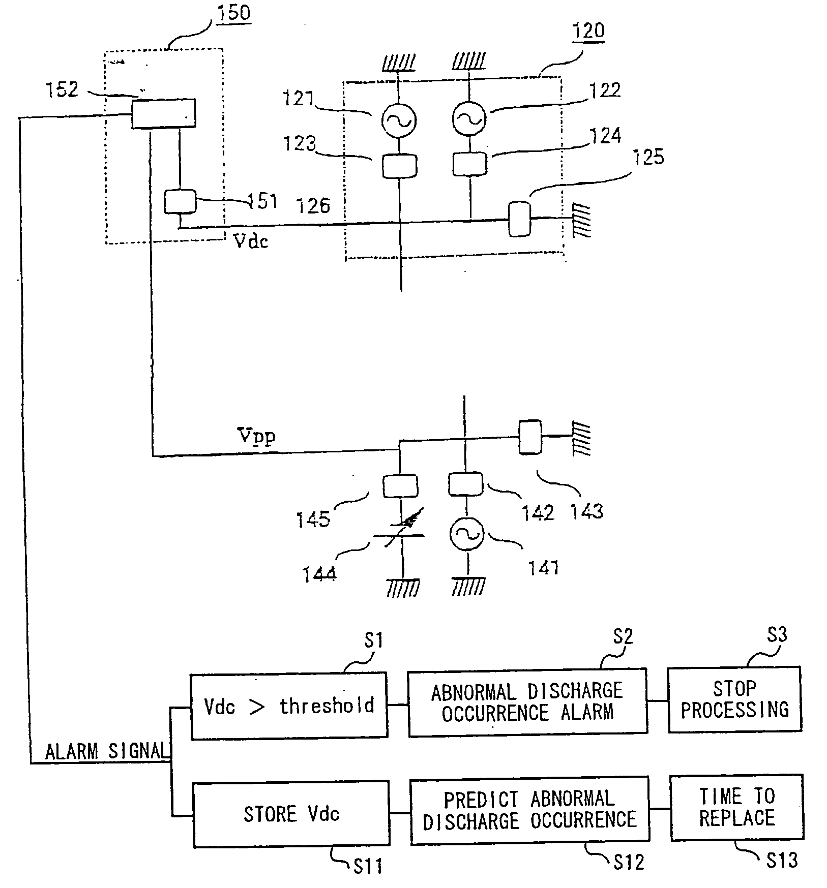
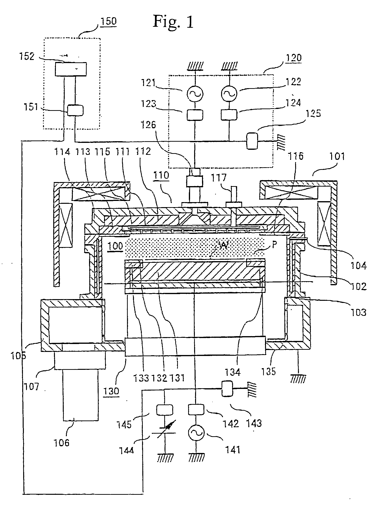
[0022] Now, a preferred embodiment of this invention will be described with reference to the accompanying drawings. FIG. 1 shows an apparatus for monitoring a plasma processing apparatus according to the embodiment of this invention, in which the plasma processing apparatus is a magnetic field UHF band electromagnetic wave radiation discharge type plasma etching apparatus. In this drawing, the plasma etching apparatus is schematically shown in section.

[0023] In FIG. 1, a process chamber 100 of the plasma processing apparatus is a vacuum container capable of attaining a degree of vacuum on the order of 10−5 Torr. An antenna 110 (upper electrode) for radiating electromagnetic waves is provided at the upper part of the process chamber, and a lower electrode 130 on which a sample W, such as a wafer, is to be mounted is provided at the lower part thereof. The antenna 110 and the lower electrode 130 are disposed in parallel facing each other. Magnetic field generator means 101, which is ...


PUM

PropertyMeasurementUnit
Bias potentialaaaaaaaaaa

Abstract

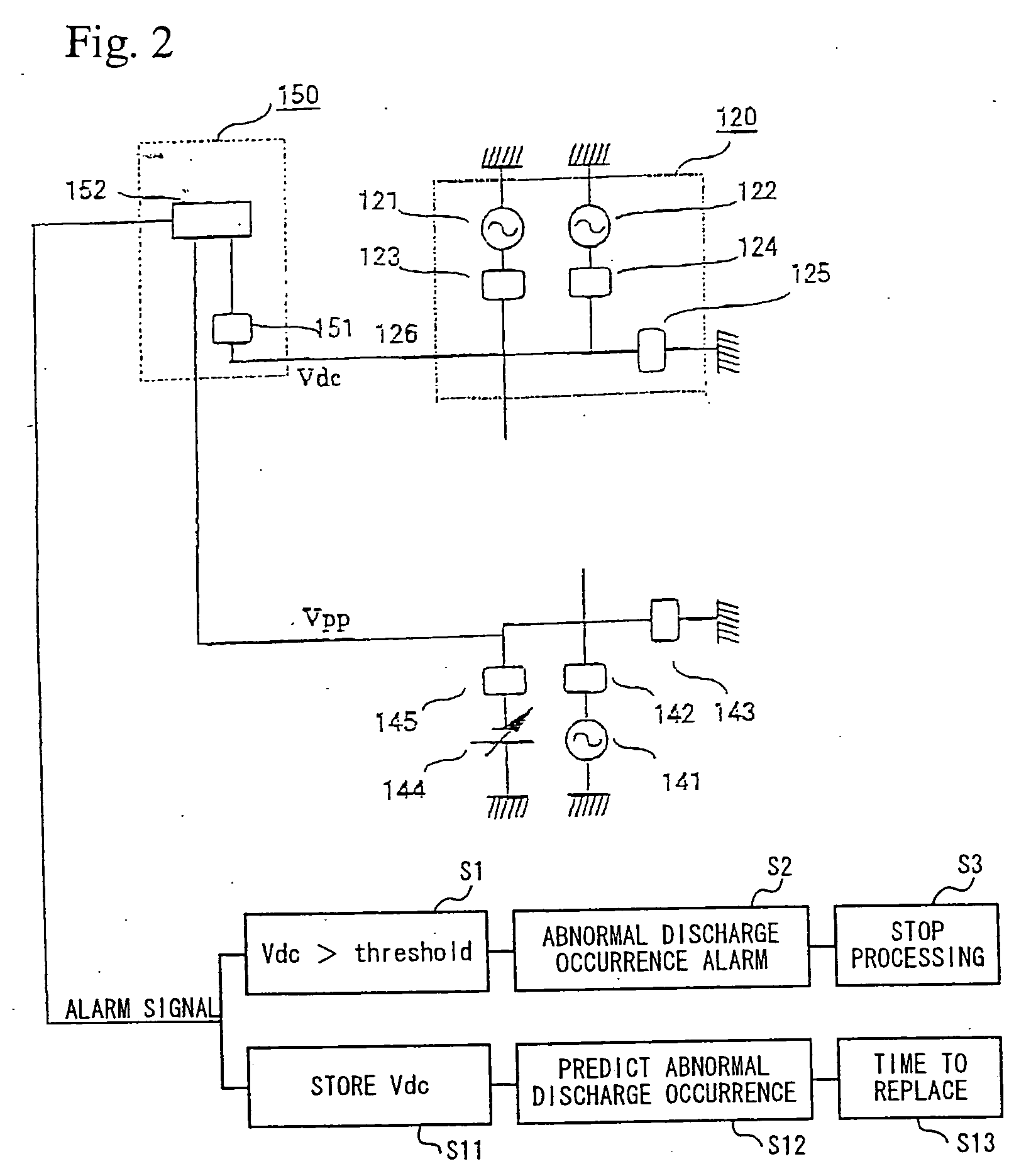
The present apparatus comprises a vacuum process chamber 100 that contains an upper electrode 110 having a conductive plate 115 with gas supply holes for supplying a process gas and a lower electrode 130 having a platform on which a sample is to be mounted; process gas supply means 117 for supplying the process gas to the gas supply holes in the upper electrode 110 and exhaust means 106 for exhausting the vacuum process chamber; a high frequency power supply 121 for applying a high frequency power to the upper electrode to generate a plasma between the upper and lower electrodes; a high frequency bias power supply 122 for applying a high frequency power to the upper electrode to generate a direct current bias potential in the upper electrode; and abnormal discharge determination means 152 for determining whether an abnormal discharge has occurred or not based on the direct current bias potential generated in the upper electrode.

Description

BACKGROUND OF THE INVENTION [0001] 1. Field of the Invention [0002] The present invention relates to the apparatus and method for monitoring a plasma processing apparatus. In particular, it relates to the apparatus and method for monitoring a plasma processing apparatus that reduces the processing failure caused by an abnormal discharge. [0003] 2. Description of the Related Art [0004] In semiconductor manufacturing processes, plasma processing apparatus are widely used for micromachining processes, such as etching, film deposition and ashing. In a process involving plasma processing, a process gas introduced into a vacuum chamber (reactor) is changed into a plasma by plasma generator means and the plasma is caused to react with a surface of a semiconductor wafer to implement micromachining, and a volatile reaction product is discharged, thereby accomplishing the predetermined process. [0005] With such a plasma processing apparatus, if the apparatus is used for a long time, component...

Claims


Application Information

Patent Timeline
IPC IPC(8): H01J37/32H01L21/3065H01L21/66
CPCH01J37/32935H01J37/32009H01L22/00
Inventor SASAKI, ICHIROMASUDA, TOSHIOFURUSE, MUNEOYAMAMOTO, HIDEYUKI
Owner SASAKI ICHIRO
Learn More