
Plasma processing method and apparatus

a technology of plasma and processing method, applied in the field of plasma processing method, can solve the problems of difficult to obtain uniform plasma generation and difficulty in obtaining uniform plasma generation

Inactive Publication Date: 2009-04-07
PANASONIC CORP
View PDF23 Cites 134 Cited by
  • Summary
  • Abstract
  • Description
  • Claims
  • Application Information

AI Technical Summary

Benefits of technology

"The present invention provides a plasma processing method and apparatus that can generate uniform plasma. This is achieved by controlling the plasma distribution on the substrate using a plasma trap with a groove-like structure. The plasma can be generated by supplying high-frequency power to a counter electrode while controlling the pressure in the vacuum chamber. The plasma can be controlled by adjusting the area of the plasma trap, the depth of the plasma trap, the width of the plasma trap, the thickness of the plasma trap, the frequency of the high-frequency power, the placement of the substrate electrode, the placement of the plasma trap, the use of a dielectric window, the use of an antenna, the use of a high-frequency power supply, and the absence of DC magnetic fields. The plasma processing method and apparatus can be used for various plasma processing applications such as plasma enhanced chemical vapor deposition and plasma assisted chemical vapor deposition."

Problems solved by technology

However, there has been an issue that the conventional methods shown in FIGS. 15 and 16 have difficulty in obtaining uniform plasma generation.
However, there has been an issue that the conventional method shown in FIG. 24 has difficulty in obtaining uniform plasma generation.

Method used


Image

  • Plasma processing method and apparatus
  • Plasma processing method and apparatus
  • Plasma processing method and apparatus

Examples


first embodiment

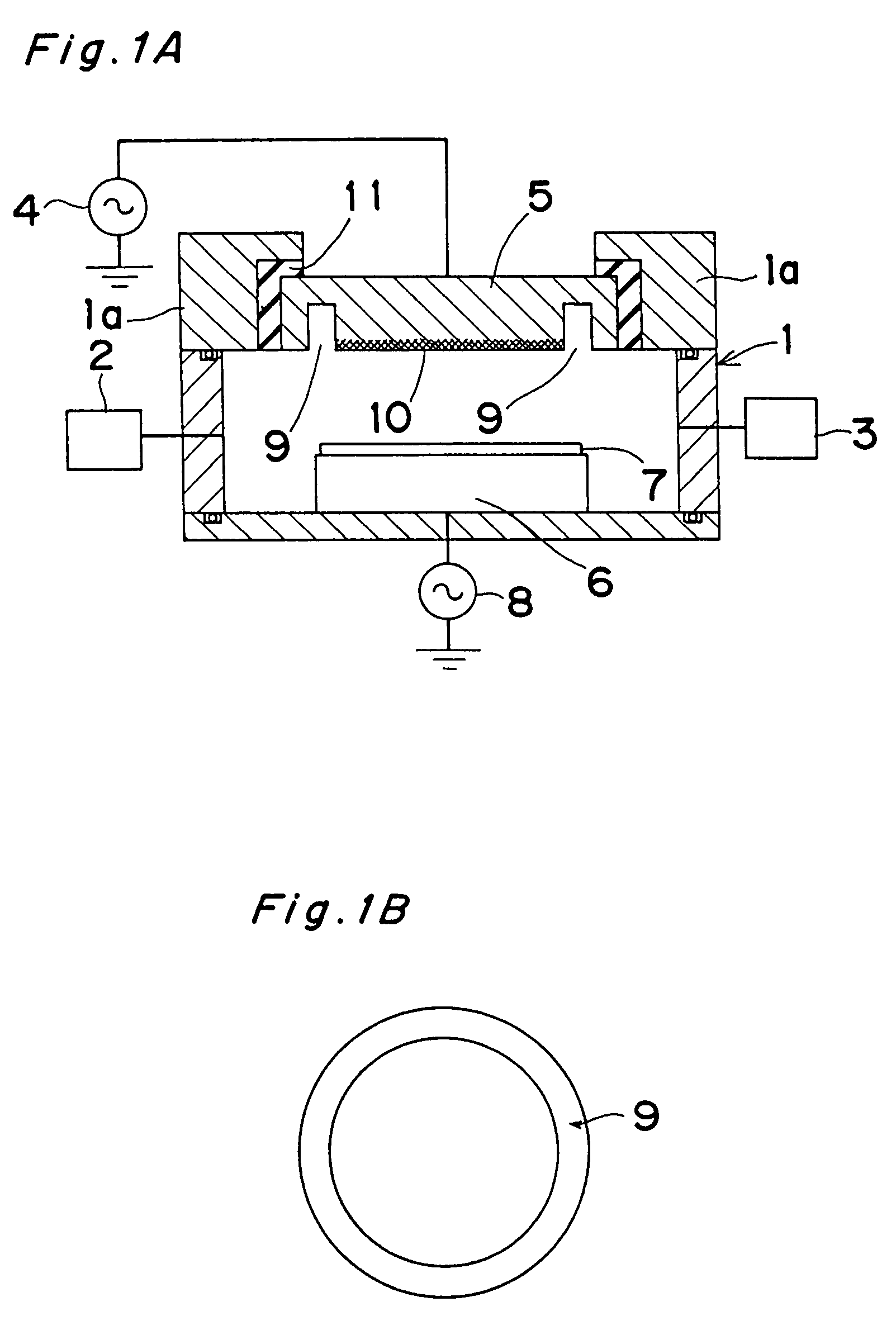
[0114]the present invention is described below with reference to FIGS. 1A, 1B, and 2.

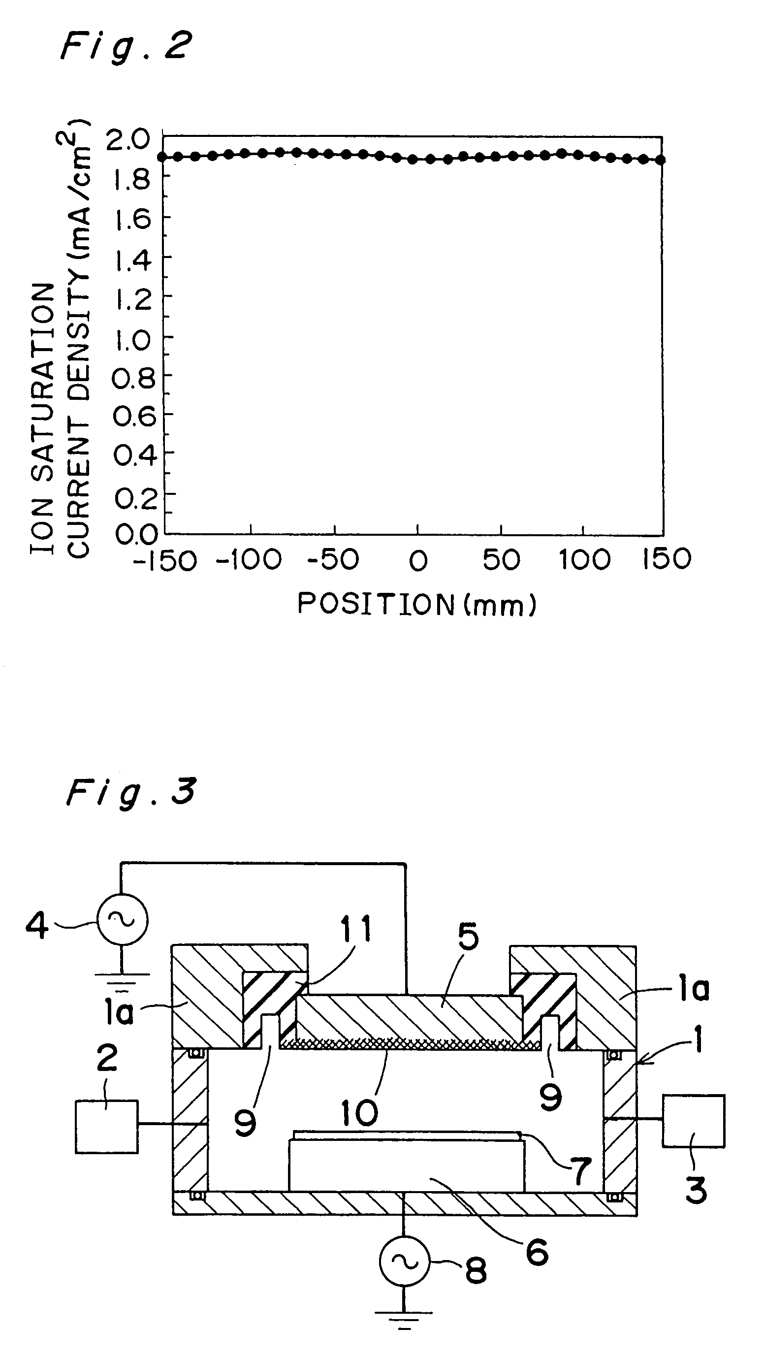
[0115]FIG. 1A shows a sectional view of a plasma processing apparatus employed in the first embodiment of the present invention. Referring to FIG. 1A, while the interior of a vacuum chamber 1 is maintained at a specified pressure by introducing a specified gas from a gas supply unit 2 into the vacuum chamber 1 and by simultaneously performing evacuation by a pump 3 as an evacuating device, a high-frequency power of 100 MHz is supplied to a counter electrode 5 by a counter-electrode-use-high-frequency power supply 4. Then, plasma is generated in the vacuum chamber 1, where plasma processing such as etching, deposition, and surface reforming can be carried out on a substrate 7 placed on a substrate electrode 6. A substrate-electrode-use-high-frequency power supply 8 for supplying high-frequency power to the substrate electrode 6 is also provided, so that ion energy that reaches the substrate 7 can be ...

tenth embodiment

[0141]Now the present invention is described below with reference to FIGS. 19 and 20.

[0142]FIG. 19 shows a sectional view of a plasma processing apparatus employed in the tenth embodiment of the present invention. Referring to FIG. 19, while the interior of a vacuum chamber 101 is maintained at a specified pressure by introducing a specified gas from a gas supply unit 102 into the vacuum chamber 101 and simultaneously performing evacuation by a pump 103 as an evacuating device, a high-frequency power of 100 MHz is supplied to a counter electrode 107 by a counter-electrode-use-high-frequency power supply 104 via a matching box 105 and a high-frequency coupling device (mount) 106. Then, plasma is generated in the vacuum chamber 101, where plasma processing such as etching, deposition, and surface reforming can be carried out on a substrate 109 placed on a substrate electrode 108. A substrate-electrode-use-high-frequency power supply 110 for supplying high-frequency power to the substr...


PUM

PropertyMeasurementUnit
frequencyaaaaaaaaaa
widthaaaaaaaaaa
frequencyaaaaaaaaaa

Abstract

The interior of a vacuum chamber is maintained at a specified pressure by introducing a specified gas into the vacuum chamber having a plasma trap provided therein. Simultaneously, therewith, evacuation of the chamber is performed by a pump as an evacuating device, and a high-frequency power of 100 MHz is supplied to a counter electrode by counter-electrode use high-frequency power supply. Thus, uniform plasma is generated within the vacuum chamber, where plasma processing such as etching, deposition, and surface reforming can be carried out uniformly with a substrate placed on a substrate electrode.

Description

[0001]This application is a divisional application of Ser. No. 09 / 511,398, filed Feb. 23, 2000 now U.S. Pat. No. 6,808,759.BACKGROUND OF THE INVENTION[0002]The present invention relates to plasma processing methods such as dry etching, sputtering, and plasma CVD, as well as apparatuses therefor, to be used for manufacture of semiconductor or other electron devices and micromachines. More particularly, the present invention relates to a plasma processing method and apparatus for the use of plasma excited with high-frequency power of VHF or UHF band.[0003]The present invention further relates to a matching box for a plasma processing apparatus to be used for impedance matching in supplying high-frequency power of VHF band, in particular, to a counter electrode for plasma excitation or to an antenna, and relates to a plasma processing method and apparatus using plasma excited with the high-frequency power of VHF band.[0004]Japanese Laid-Open Patent Publication No. 8-83696 describes tha...

Claims


Application Information

Patent Timeline
Patent Type & Authority Patents(United States)
IPC IPC(8): C23C16/00H05H1/46C23C16/505H01J37/32
CPCC23C16/505H01J37/32623H05H1/30
Inventor OKUMURA, TOMOHIROHARAGUCHI, HIDEOMATSUI, TAKUYAMATSUDA, IZURUMITSUHASHI, AKIO
Owner PANASONIC CORP
Learn More