
Toilet ventilation system and method

a technology for ventilating systems and toilets, applied in water installations, lavatory sanitory, construction, etc., can solve the problems of not being able to effectively remove odors from toilets, not being able to maintain a high level of cleanliness, and not being able to achieve the effect of reducing the number of toilets

Inactive Publication Date: 2005-03-10
THOMAS KIRK M
View PDF18 Cites 40 Cited by
  • Summary
  • Abstract
  • Description
  • Claims
  • Application Information

AI Technical Summary

Benefits of technology

[0006] It has been recognized that it would be advantageous to develop a toilet ventilation system that is simple and inexpensive, and does not require significant maintenance, and that effectively draws odors away from a bathroom toilet.

Problems solved by technology

Toilet odors can be a great bother and nuisance.
A home or other building that is kept to very high standards of cleanliness can still smell foul due to toilet odors.
Unfortunately, typical bathroom exhaust fans are only minimally effective at removing these odors.
The long distance and small flow rate of air through the fan mean that a relatively long time is needed for bathroom exhaust fans to have a significant effect.
Moreover, some bathroom fans are not actually connected to an external exhaust outlet.
Such fans merely stir the air in the room, and have very little effect in eliminating odors.
Unfortunately, many prior systems have a number of drawbacks.
Many of them are quite complicated, with complex piping schemes, pumps, filters, drains, etc.
These and other systems include components that must be replaced on a regular basis, creating a maintenance headache.

Method used


Image

  • Toilet ventilation system and method
  • Toilet ventilation system and method
  • Toilet ventilation system and method

Examples


Embodiment Construction

[0018] Reference will now be made to the exemplary embodiments illustrated in the drawings, and specific language will be used herein to describe the same. It will nevertheless be understood that no limitation of the scope of the invention is thereby intended. Alterations and further modifications of the inventive features illustrated herein, and additional applications of the principles of the inventions as illustrated herein, which would occur to one skilled in the relevant art and having possession of this disclosure, are to be considered within the scope of the invention.

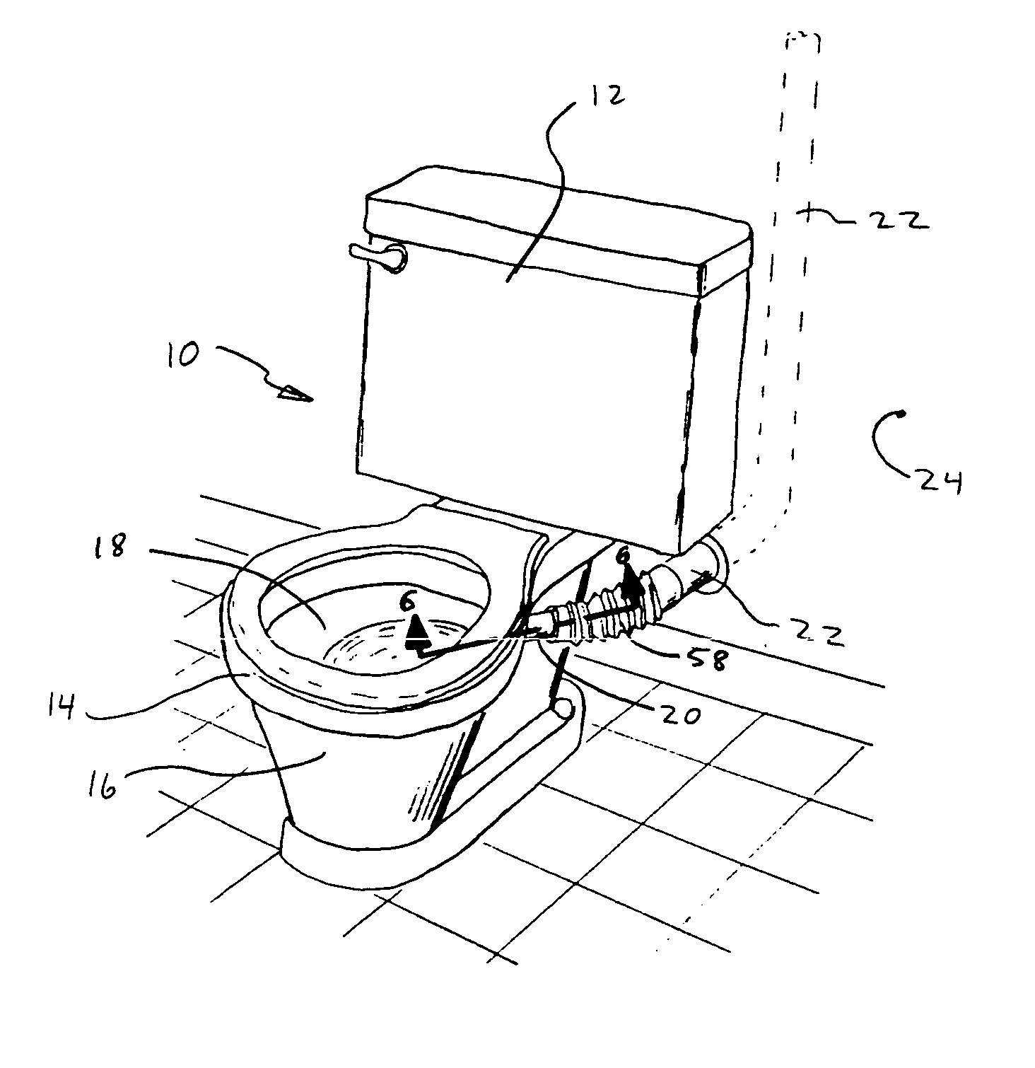
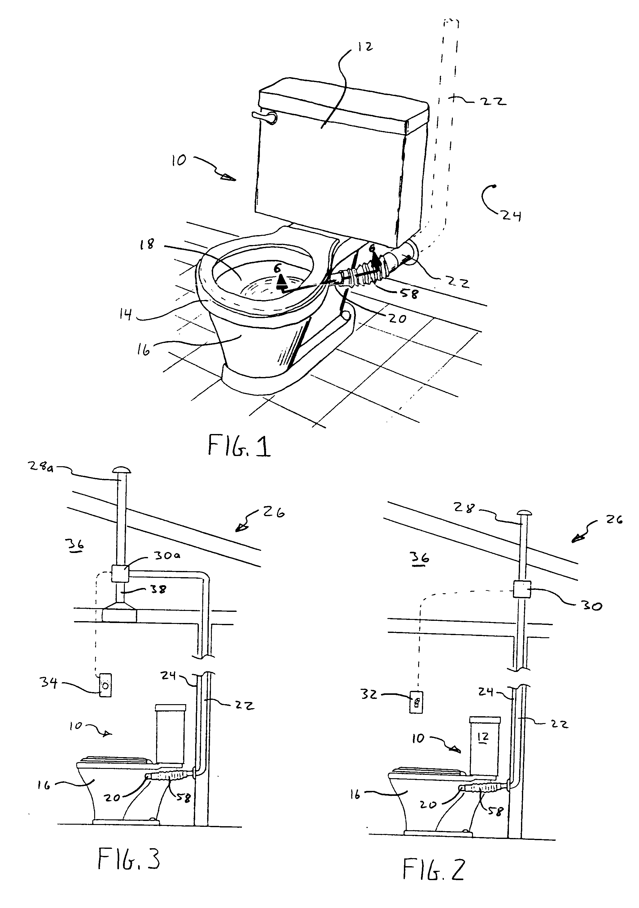
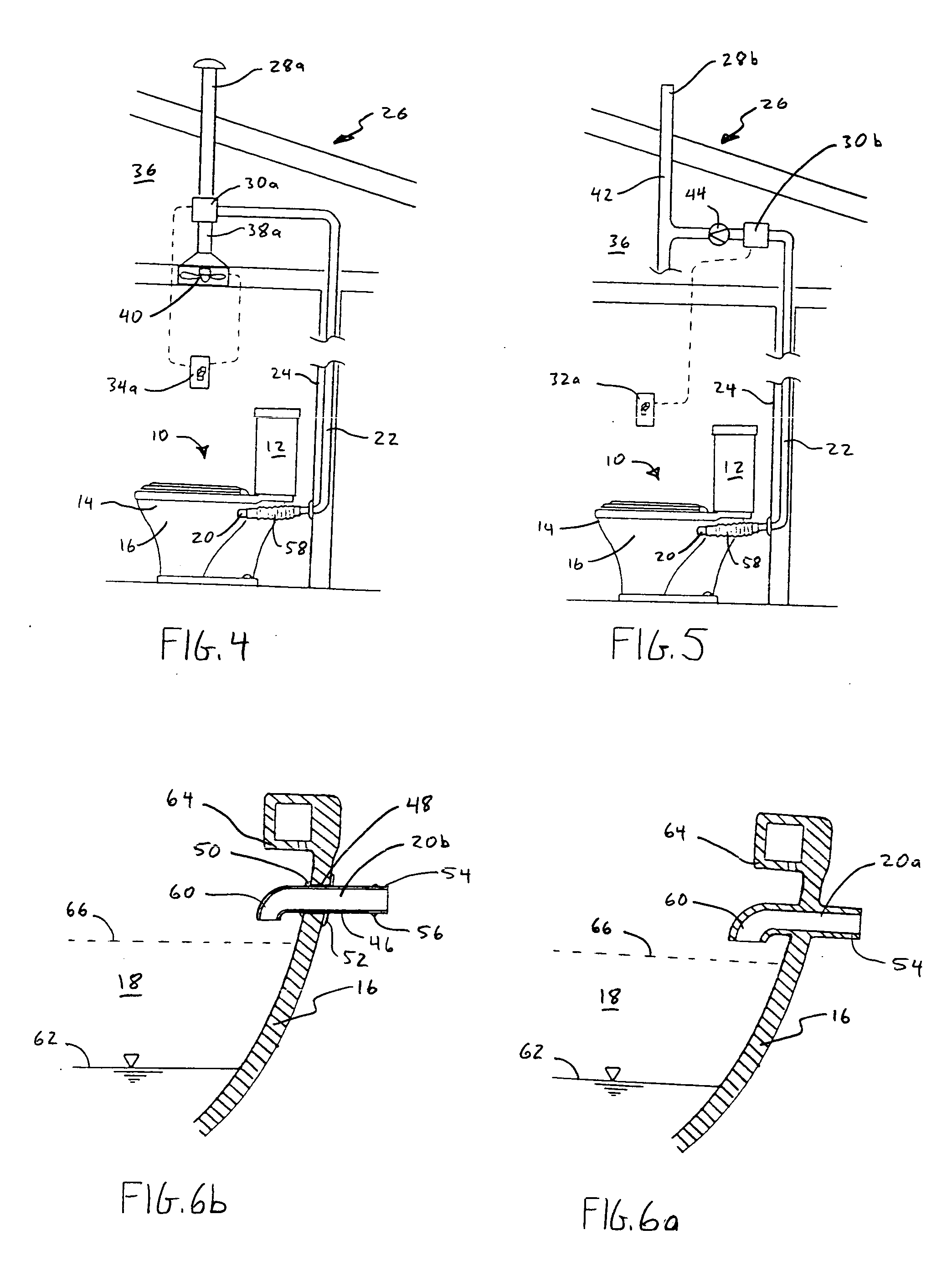
[0019] The present invention provides a toilet ventilation system configured for use with a specially configured flush toilet 10, shown in FIGS. 1 and 2. While the toilet shown includes a tank portion 12, and a toilet bowl portion 14, disposed below the tank portion, it will be apparent that the invention can be used with tankless toilets—i.e. those using a pressurized flush valve, such as are found in most pub...


PUM


Abstract

A toilet ventilation system includes a flush toilet having a toilet bowl portion including a perimeter wall enclosing an interior of the bowl. A bowl vent inlet extends through a side of the perimeter wall from the interior to the exterior of the bowl at a position above a static water level in the bowl. The bowl vent inlet has an exterior end configured to connect to a vent conduit for drawing odors out of the toilet bowl.

Description

BACKGROUND OF THE INVENTION [0001] 1. Field of the Invention [0002] The present invention relates generally to systems for ventilating toilet odors. [0003] 2. Related Art [0004] Toilet odors can be a great bother and nuisance. A home or other building that is kept to very high standards of cleanliness can still smell foul due to toilet odors. Unfortunately, typical bathroom exhaust fans are only minimally effective at removing these odors. This may be because such fans pump a relatively small volume of air, and are typically located in a bathroom ceiling, substantially removed from the source of the odors. The long distance and small flow rate of air through the fan mean that a relatively long time is needed for bathroom exhaust fans to have a significant effect. During this time, the odors can easily drift into other parts of the building. Moreover, some bathroom fans are not actually connected to an external exhaust outlet. Such fans merely stir the air in the room, and have very ...

Claims


Application Information

Patent Timeline
Patent Type & Authority Applications(United States)
IPC IPC(8): E03D9/052
CPCE03D9/052
Inventor THOMAS, KIRK M.
Owner THOMAS KIRK M
Learn More