
Power throttling method and apparatus

a power throttling and power technology, applied in the direction of liquid/fluent solid measurement, high-level techniques, instruments, etc., can solve the problems of power waste, dc leakage component not being helped, and a considerable amount of software being used

Inactive Publication Date: 2005-02-24
IBM CORP
View PDF6 Cites 42 Cited by
  • Summary
  • Abstract
  • Description
  • Claims
  • Application Information

AI Technical Summary

Benefits of technology

[0009] The present invention comprises using a CPU architecture control mechanism which shuts down at least one of active AC power and DC leakage compo

Problems solved by technology

However, it does not help the DC leakage component because there is still voltage being applied to the circuits.
However, even though the width has increased, there remains a considerable amount of software being used which is written for a previous generation's smaller width.
However, even though a portion of the instruction set hardware is not being used, it still, in all known present day CPUs, is using electrical power.
Since the power being used is not actively assisting the software, this power is being wasted.

Method used


Image

  • Power throttling method and apparatus
  • Power throttling method and apparatus
  • Power throttling method and apparatus

Examples


Embodiment Construction

[0013] In the following discussion, numerous specific details are set forth to provide a thorough understanding of the present invention. However, those skilled in the art will appreciate that the present invention may be practiced without such specific details. In other instances, well-known elements have been illustrated in schematic or block diagram form in order not to obscure the present invention in unnecessary detail. Additionally, for the most part, details concerning network communications, electromagnetic signaling techniques, and the like, have been omitted inasmuch as such details are not considered necessary to obtain a complete understanding of the present invention, and are considered to be within the understanding of persons of ordinary skill in the relevant art.

[0014] It is further noted that, unless indicated otherwise, all functions described herein may be performed in either hardware or software, or some combination thereof. In a preferred embodiment, however, t...


PUM


Abstract

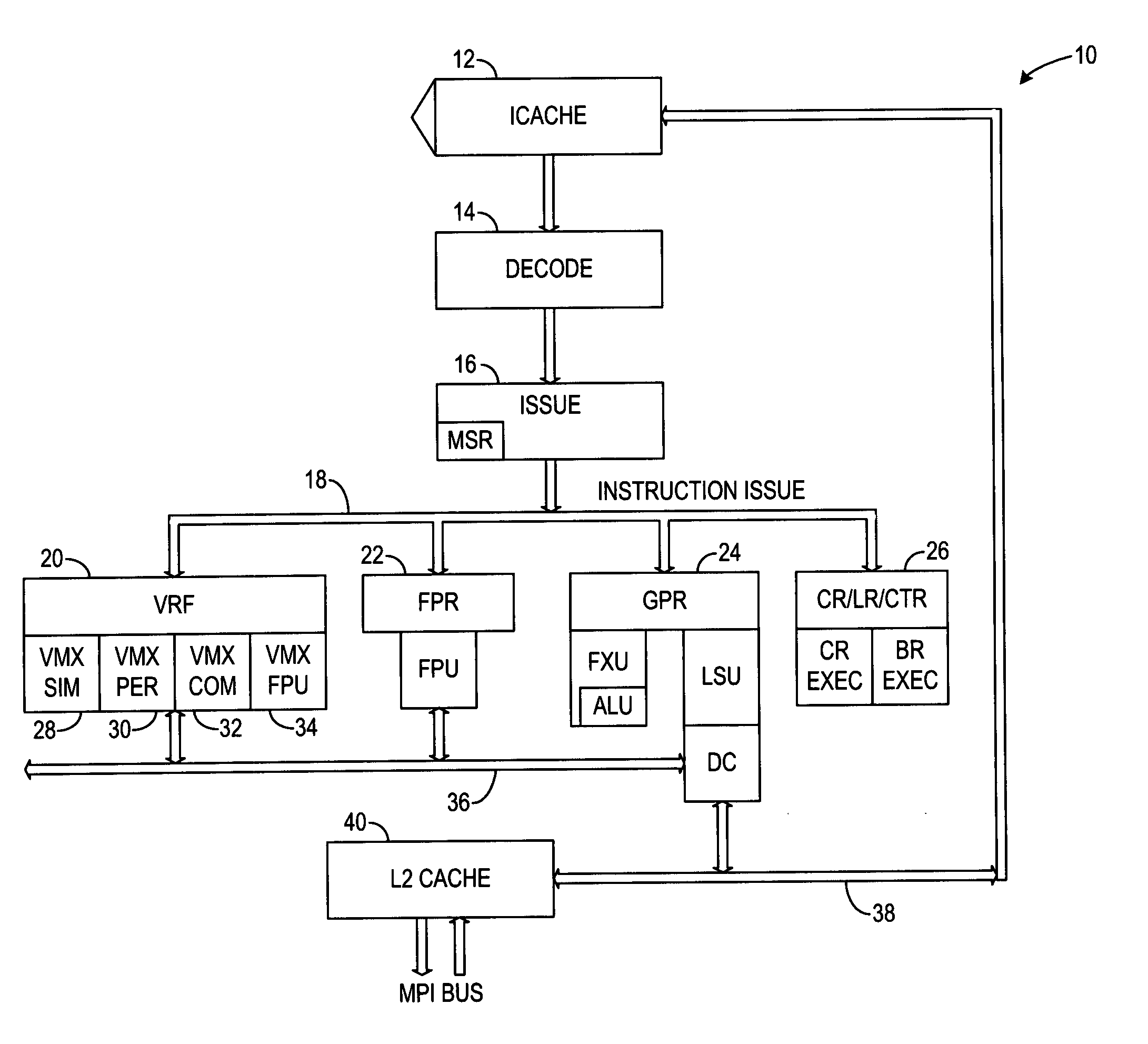
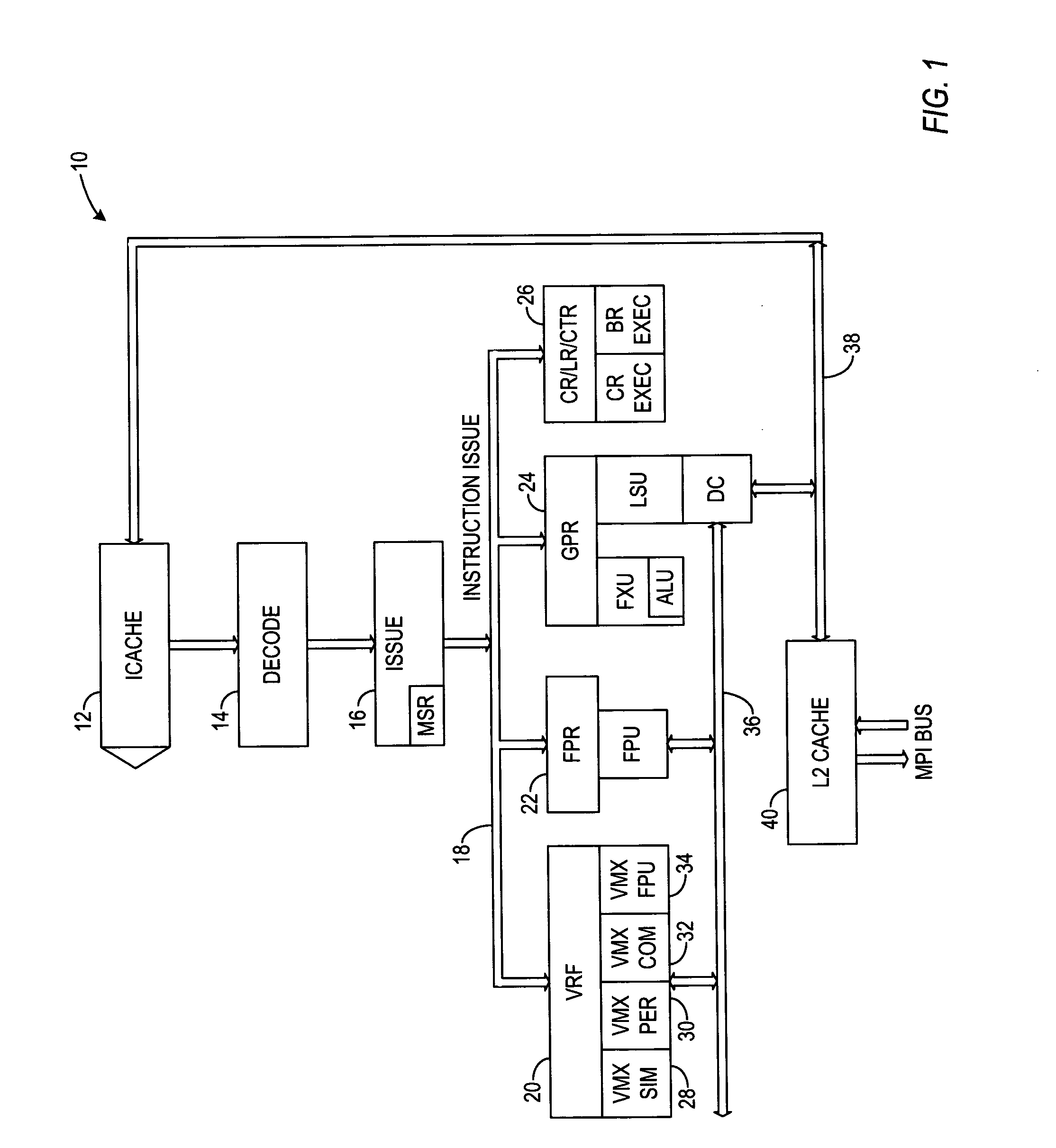
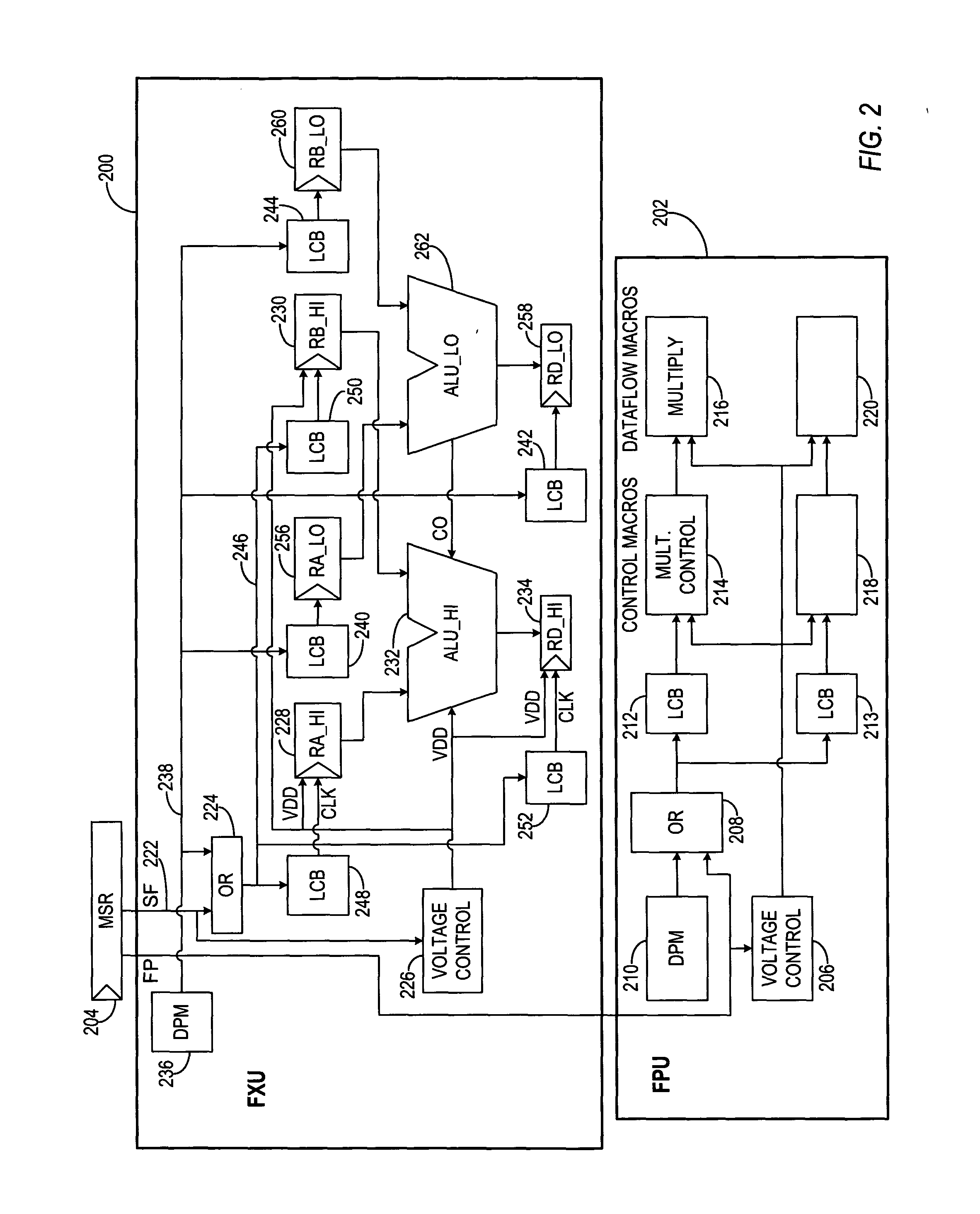
Disclosed is an apparatus which deactivates both the AC as well as the DC component of power for various functions in a CPU. The CPU partitions dataflow registers and arithmetic units such that voltage can be removed from the upper portion of dataflow registers when the software is not utilizing same. Clock signals are also prevented from being applied to these non-utilized components. As an example, if a 64 bit CPU (processor unit) is to be used with both 32 and 64 bit software, the mentioned components may be partitioned in equal sized upper and lower portions. The logic signal for activating the removal of voltage may be obtained from a software-accessible architected control register designated as a machine state register in some CPUs. The same logic may be used in connection with removing voltage and clocks from other specialized functional components such as the floating point unit when software instructions do not presently require same.

Description

TECHNICAL FIELD [0001] The invention relates to a Central Processing Unit (CPU) control and, more particularly, to reducing power usage in the CPU. BACKGROUND [0002] In the past there have been two types of power management in computers. A first type is software based which periodically checks to see if computer parts such as the keyboard, the hard disk, the CD drive, and so forth, are being used. If items like the hard drive are no longer being used, the software will typically remove power from the drive motor after a given period of non-use. If the keyboard has not been used for a given time, the display may be removed from the screen and / or power may be removed from the monitor and / or major portions of the CPU. A second type of power control has been labeled in the art as DPM (Dynamic Power Management). Instructions being processed in the computer are monitored and when there are no more instructions to be processed, a DPM module acts to remove clock signals from appropriate por...

Claims


Application Information

Patent Timeline
IPC IPC(8): G06F1/32
CPCY02B60/1282Y02B60/1278Y02B60/32G06F9/30112G06F1/3203G06F9/30141G06F1/3287G06F9/30189Y02D10/00Y02D30/50
Inventor KAHLE, JAMES ALLANSHIPPY, DAVID J.NORSTRAND, ALBERT JAMES VAN JR.
Owner IBM CORP
Learn More