
Method and apparatus for direct digital to rf conversion using pulse shaping

a technology of pulse shaping and digital to rf, applied in the direction of electrical apparatus, modulation transference, transmission, etc., can solve the problems of inability to achieve inability to achieve the performance of main image, and proportional decrease in energy per sample, etc., to achieve shorten the dac pulse, facilitate the obtaining of flat or near flat output spectrum, and reduce the loss of signal energy

Inactive Publication Date: 2005-02-24
VIENNEY CECILE +1
View PDF0 Cites 1 Cited by
  • Summary
  • Abstract
  • Description
  • Claims
  • Application Information

AI Technical Summary

Benefits of technology

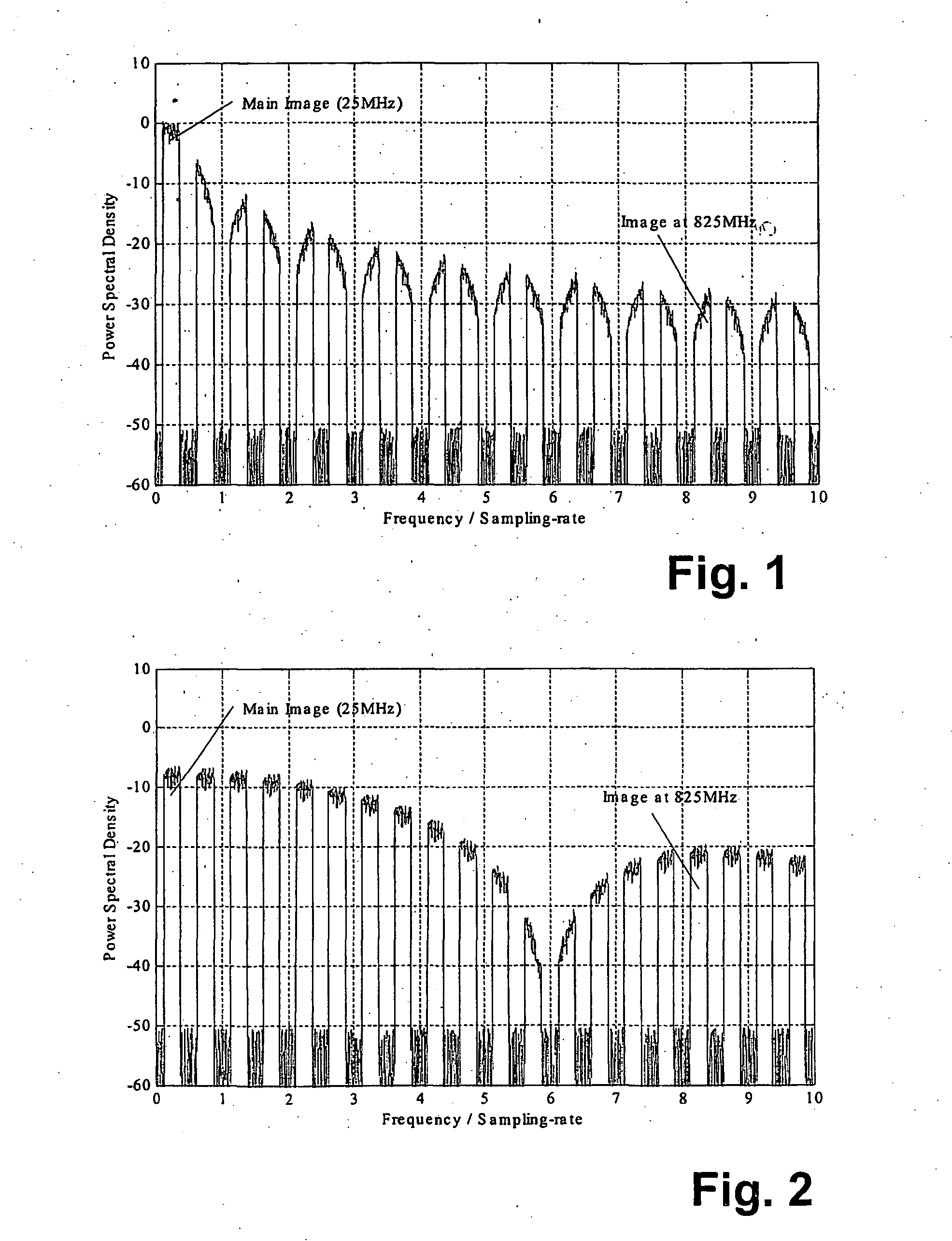
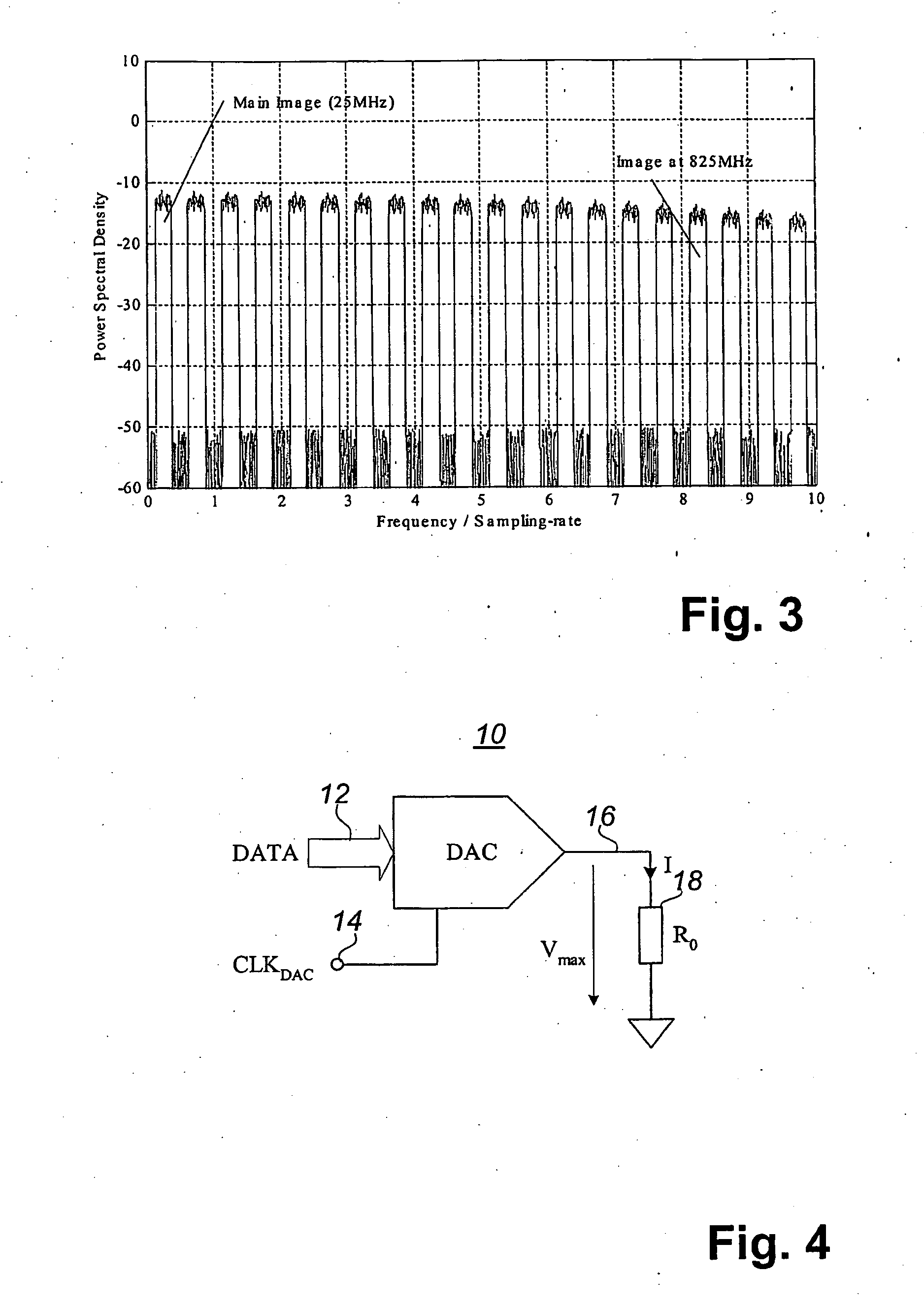
The invention described herein provides a method and apparatus that allows direct digital to IF / RF conversion using pulse-shaping. The method facilitates obtaining a flat or near flat output spectrum after digital to analog conversion with a minimal loss in signal energy. As opposed to pulse-shortening, where the DAC output pulse and consequently the energy per sample are reduced to a fraction a<1 of the maximum, the pulse-shaping does not shorten the DAC pulse. For each sample, pulse-shaping first stores the energy delivered by DAC and then releases the stored energy to the output during a short period of time aT. This way little signal energy is lost even for very small values of a. With pulse-shaping, the duration aT of the output pulse contributes to the spectral flatness in a way similar to that pulse-shortening, but has the additional benefit that the shape of the output pulse contributes significantly to a flat spectrum.

Problems solved by technology

This is not possible, because an infinitely short pulse with non-zero energy must have infinite amplitude.
Unfortunately, decreasing a causes a proportional decrease in the energy per sample, the signal power and consequently the SNR.
However, their performance cannot be better than the main image, which is already strongly attenuated.

Method used


Image

  • Method and apparatus for direct digital to rf conversion using pulse shaping
  • Method and apparatus for direct digital to rf conversion using pulse shaping
  • Method and apparatus for direct digital to rf conversion using pulse shaping

Examples


first embodiment

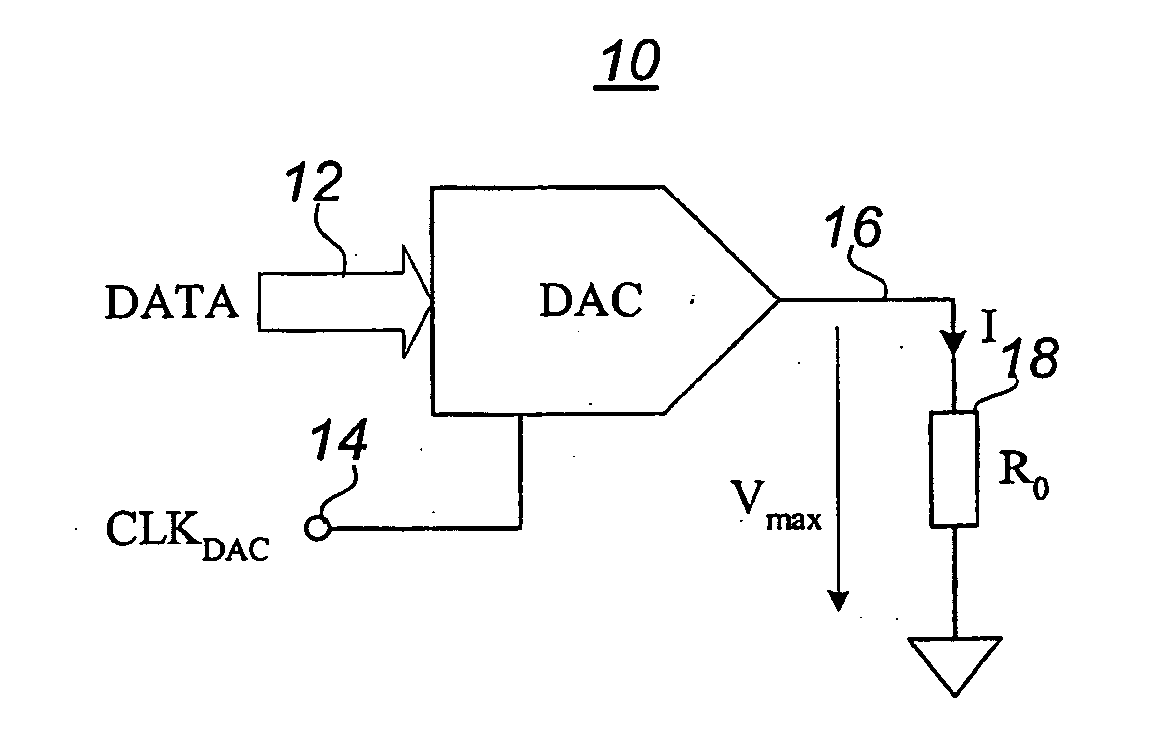
Referring to FIG. 5 there is illustrated a digital-to-analog converter (DAC) with pulse shaping in accordance with the present invention. The DAC 10 has a data port 12 a clock input 14 and in the output 16. The output 16 is coupled to the load resistor 18′ through an inductor 20. A pair of switches 22 and 24 are operable to couple either side of the inductor 20 to ground.

In operation, with the pulse shaping method as described with regard to the first embodiment of the present invention, the energy produced by a current-output DAC 10 every sample is stored in the inductor 20 during a first stage and then released from the inductor 20 to the load 18′ during a second stage. The first stage lasts for a time (1−a)T while second stage lasts for a time aT. The principle of the method is shown in FIG. 5. The inductor 20, with value L, is used to store temporarily the energy. T is the load resistor 18′, a value of R. The first switch 22 (SW1) stays closed in the first stage and opens in se...

second embodiment

Referring to FIG. 7 there is illustrated a digital-to-analog converter (DAC) with pulse-shaping in accordance with the present invention. The DAC 10 has a data port 12 a clock input 14 and in the output 16. The output 16 is coupled via first and second switches 30 and 32 to a load resistor 34. A capacitor 36 is coupled between the first and second switches 30 and 32 and ground.

In operation, with the pulse shaping method as described with regard to the second embodiment of the present invention, the energy produced by a voltage-output DAC every sample is stored in a capacitor during a first stage and then released from the capacitor to the load during a second stage. The first stage lasts a time (1−a)T while second stage lasts a time aT. The principle of the method is shown in FIG. 7. The capacitor 36 having a value C is used to temporarily store the energy output by the DAC 10. The load resistor 34 has a value R. The switch 30 (SW1) stays open during the first stage and is closed f...


PUM


Abstract

The invention described herein provides a method and apparatus that allows direct digital to IF / RF conversion using pulse-shaping. The method facilitates obtaining a flat or near flat output spectrum after digital to analog conversion with a minimal loss in signal energy. As opposed to pulse-shortening, where the DAC output pulse and consequently the energy per sample are reduced to a fraction a<1 of the maximum, the pulse-shaping does not shorten the DAC pulse. For each sample, pulse-shaping first stores the energy delivered by DAC and then releases the stored energy to the output during a short period of time aT. This way little signal energy is lost even for very small values of a. With pulse-shaping, the duration aT of the output pulse contributes to the spectral flatness in a way similar to that pulse-shortening, but has the additional benefit that the shape of the output pulse contributes significantly to a flat spectrum. Two embodiments of the pulse-shaping method are described in the context of two types of DAC that are used: one with current output and the other with voltage output. Then, two examples of pulse-shaping implementation are given for a single-ended current-output DAC and for a differential current-output DAC.

Description

FIELD OF THE INVENTION The present invention relates to wireless data communications systems and is particularly concerned with direct digital to RF conversion. BACKGROUND OF THE INVENTION With advances in digital technology and digital signal processing, more and more functionality is moved from analog circuits to digital circuits. This has many advantages including higher integration, steeper costs descend, accuracy, repeatability and reliability. Digital communications is one the fields that have both driven and tremendously benefited from this trend. Many digital receivers today utilize IF (intermediate frequency) or RF (radio frequency) sampling to reduce the number of analog components to a minimum. With IF / RF sampling, the sample and hold (S / H) analog to digital converter (ADC) samples and quantize directly the IF / RF signal as opposed to base-band sampling where the signal is first down-converted to base-band (low frequencies), filtered and that sampled. IF / RF sampling pro...

Claims


Application Information

Patent Timeline
Patent Type & Authority Applications(United States)
IPC IPC(8): H03D7/00H04B1/04H04B1/28
CPCH03D7/00H04B1/28H04B1/04
Inventor VIENNEY, CECILEDE CONINCK, CEDRIC
Owner VIENNEY CECILE
Learn More