On-device random number generator

Inactive Publication Date: 2005-02-24
TEXAS INSTR INC
View PDF18 Cites 14 Cited by
  • Summary
  • Abstract
  • Description
  • Claims
  • Application Information

AI Technical Summary

Benefits of technology

[0013] The present invention provides significant advantages over the prior art. The key is generated internal to the integrated circuit and is therefore not known to manufacturing personnel. External access to the key, eithe

Problems solved by technology

Because the key is accessible only internally, it cannot be easily discovered from external means without destruction of the integrated circuit.

Method used


Image

  • On-device random number generator
  • On-device random number generator

Examples


Embodiment Construction

[0017] The present invention is best understood in relation to FIGS. 1-2 of the drawings, like numerals being used for like elements of the various drawings.

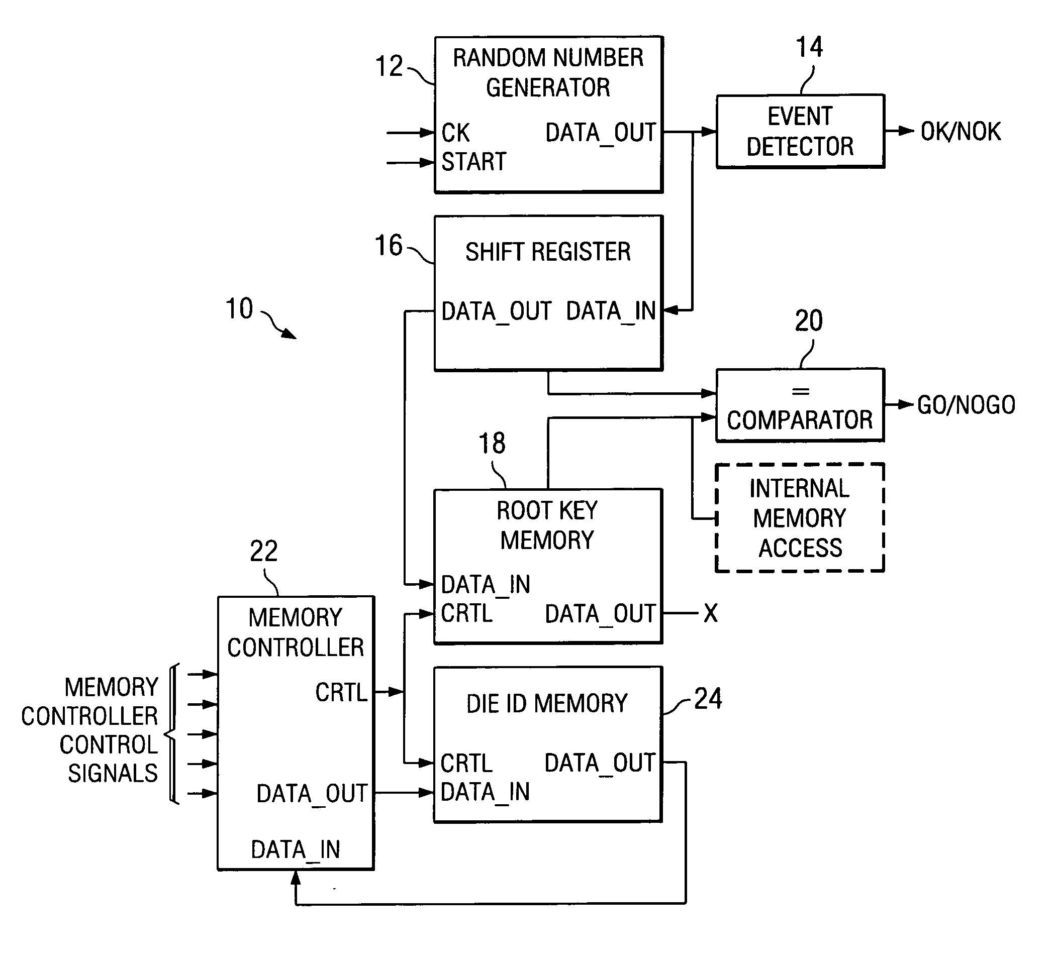
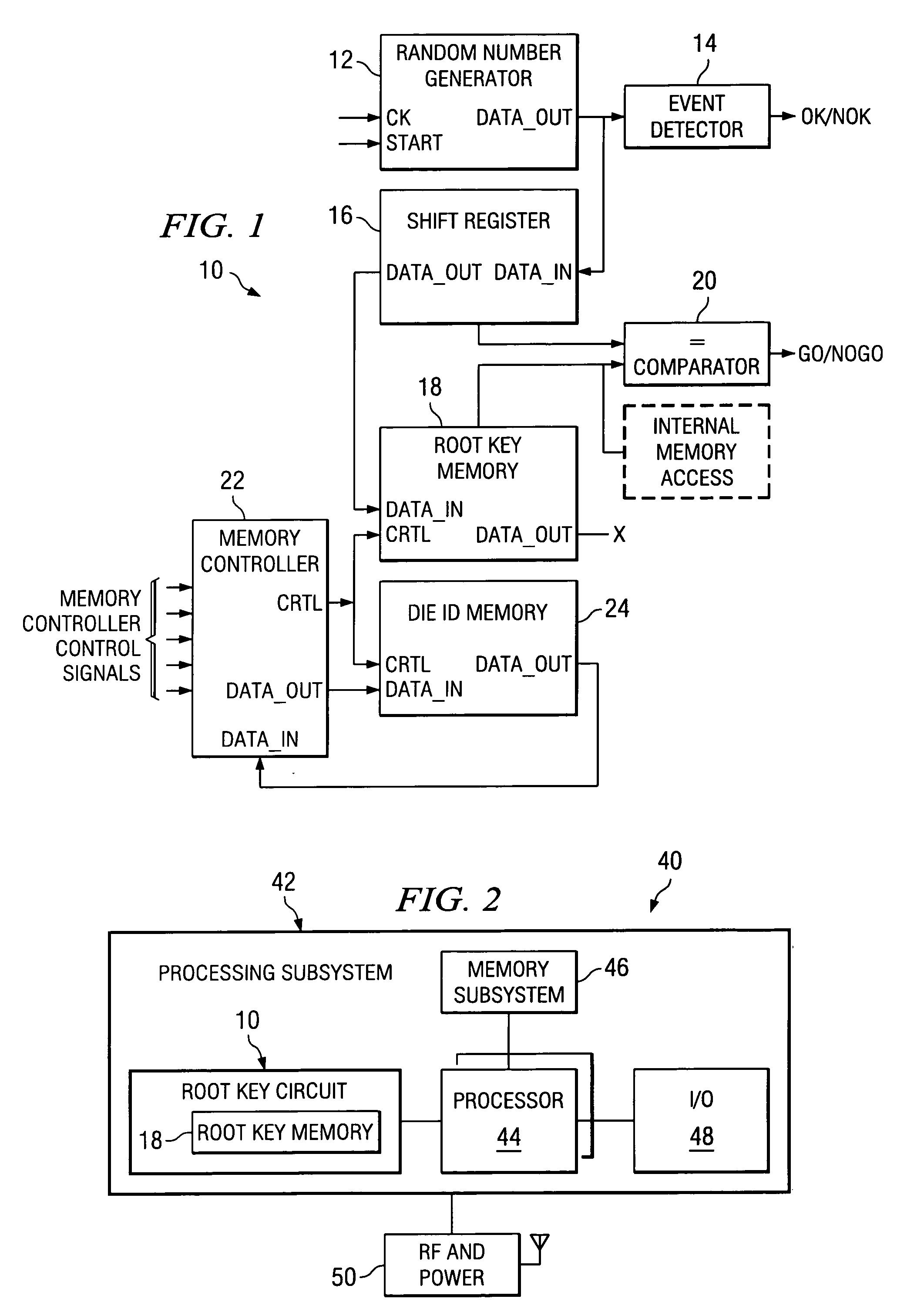
[0018]FIG. 1 illustrates a block diagram of a random key circuit 10 for non-volatile storage of a random key on a processing circuit. A random number generator 12 generates a random number in response to clock (CK) and Start signals. An event detector 14 and a shift register 16 receive the output of the random number generator 12. The shift register 16 outputs a serial representation of the random number to a root key memory 18. Parallel outputs from the shift register 16 and Root Key memory 18 are input to a comparator 20. The serial output of the shift register 16 are stored in the root key memory 18 under control of a memory controller 22. The memory controller 22 can also be used to store the die ID in a Die ID memory 24 (not part of the random key circuit 10). The output of the Die ID memory 24 is received by the memory co...


PUM


Abstract

A random key generator circuit (10) generates a random number internal to an integrated circuit and stores the random number as a “root key” in a memory (18) on the integrated circuit. The output of the Root Key memory (18) is only accessible internal to the integrated circuit. The root key can be permanently stored in a fused memory or other memory type which is protected from erasure or reprogramming once the root key is stored.

Description

CROSS-REFERENCE TO RELATED APPLICATIONS [0001] Not Applicable STATEMENT OF FEDERALLY SPONSORED RESEARCH OR DEVELOPMENT [0002] Not Applicable BACKGROUND OF THE INVENTION [0003] 1. Technical Field [0004] This invention relates in general to electronic circuits and, more particularly, to a random number generator circuit with permanent storage. [0005] 2. Description of the Related Art [0006] In many processing devices, such as computers, PDAs (personal digital assistants), mobile phones, and smart phones, it is necessary to maintain complete secrecy of certain data. One application, for example, would be financial transactions, where important information may stored on the processing device or a memory external to the processing device. It is important that a third party could not access the processing device's memory in order to ascertain sensitive information. In some cases, there may be a need for information to be stored on the processing device that is to be maintained in secrecy ...

Claims


Application Information

Patent Timeline
IPC IPC(8): G06F7/58G06F21/73
CPCG06F21/73G06F7/58
Inventor CHATEAU, ALAINDAHAN, FRANCK
Owner TEXAS INSTR INC
Why Eureka
Try Eureka