
Objective lens for optical recording media and optical pickup device using it

a technology which is applied in the field of optical recording media and optical pickup device using it, can solve the problems of increasing the amount of data that is handled in everyday life, increasing the amount of data that is available on optical recording media, and becoming urgent, so as to increase the freedom of selecting the position

Inactive Publication Date: 2005-02-24
FUJI PHOTO OPTICAL CO LTD
View PDF9 Cites 13 Cited by
  • Summary
  • Abstract
  • Description
  • Claims
  • Application Information

AI Technical Summary

Benefits of technology

The present invention relates to an objective lens for optical recording media that increases the freedom in selecting the position of the optical system, including the objective lens, that is usable for recording and reproducing data from any one of three different optical recording media using light beams of three different wavelengths and with three different numerical apertures of the objective lens, and that assures that the light beam of each different wavelength efficiently focuses at a respective desirable position on the corresponding optical recording medium by properly forming a lens surface as a optical diffractive surface. Efficient focusing is obtained even though the disk thicknesses of the three recording media may be different. The present invention further relates to an optical pickup device that uses such an objective lens.

Problems solved by technology

As the amount of data that is handled in everyday life rapidly increases, demands for increasing the amount of data optical recording media can record become urgent.
However, it is difficult to satisfy the condition discussed above that each light beam of a different wavelength from a light source for illuminating one of each of three different optical recording media be incident on the objective lens as a substantially parallel beam according to the teachings of Japanese Patent Application 2003-91382 and Japanese Laid-Open Patent Application 2003-67972 discussed above.
In particular, objective lenses according to Japanese Patent Application 2003-91382 and Japanese Laid-Open Patent Application 2003-67972 may be arranged so that the light beams having wavelengths in use relative to one or two types of optical recording media are incident onto the objective lens as substantially parallel beams in order to favorably record or reproduce data on the different optical recording media, but it is technically difficult to achieve a substantially parallel incident beam when three different recording media are used.

Method used


Image

  • Objective lens for optical recording media and optical pickup device using it
  • Objective lens for optical recording media and optical pickup device using it
  • Objective lens for optical recording media and optical pickup device using it

Examples


Embodiment Construction

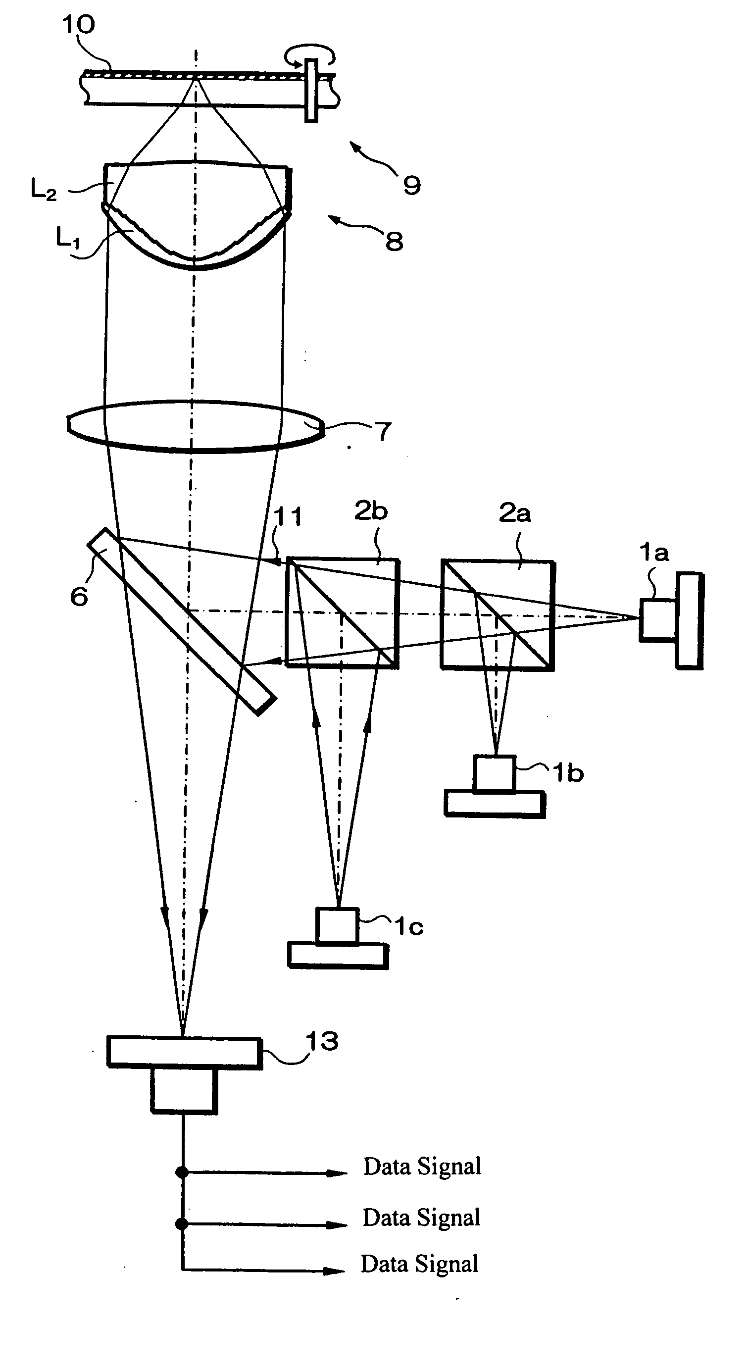
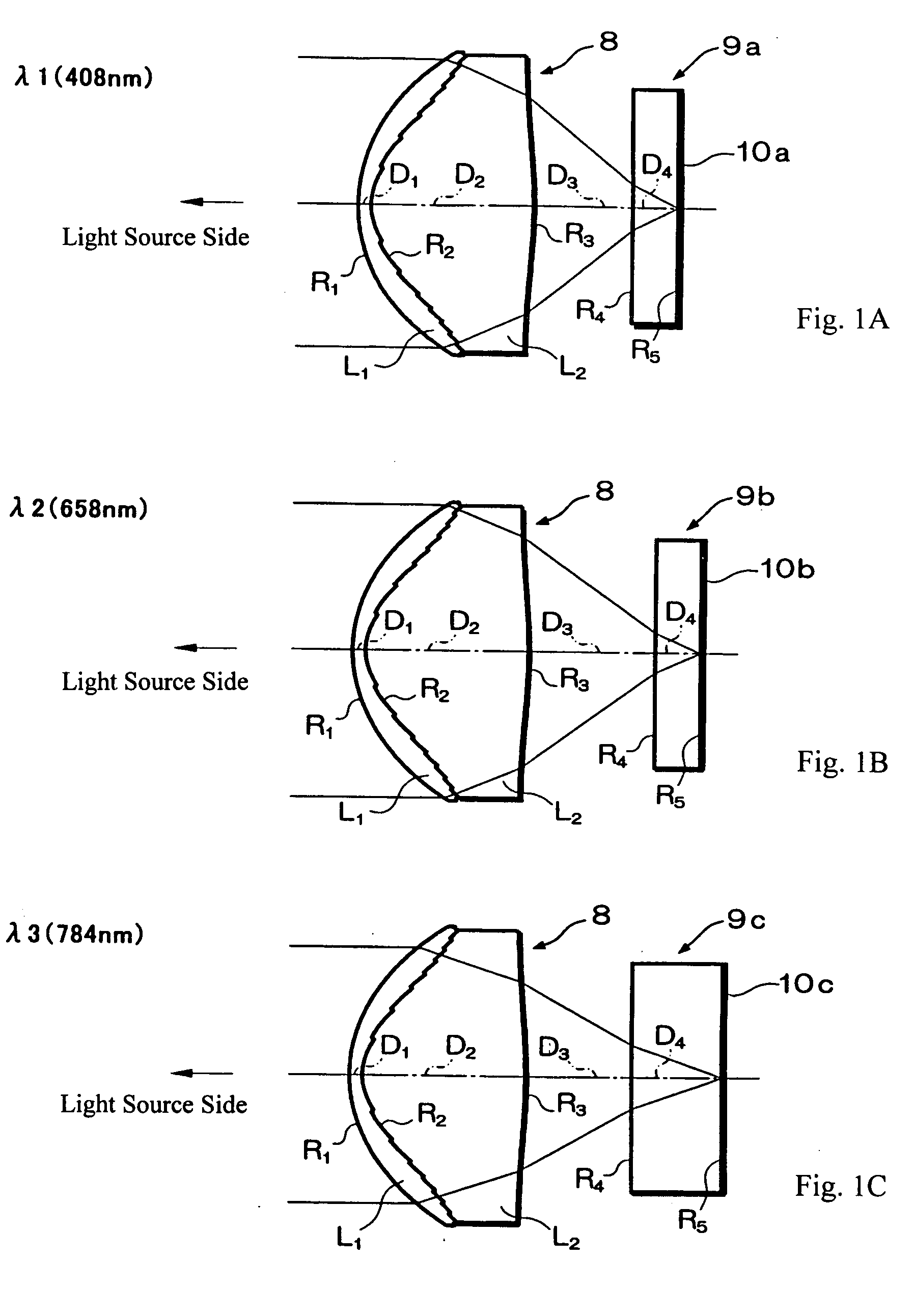
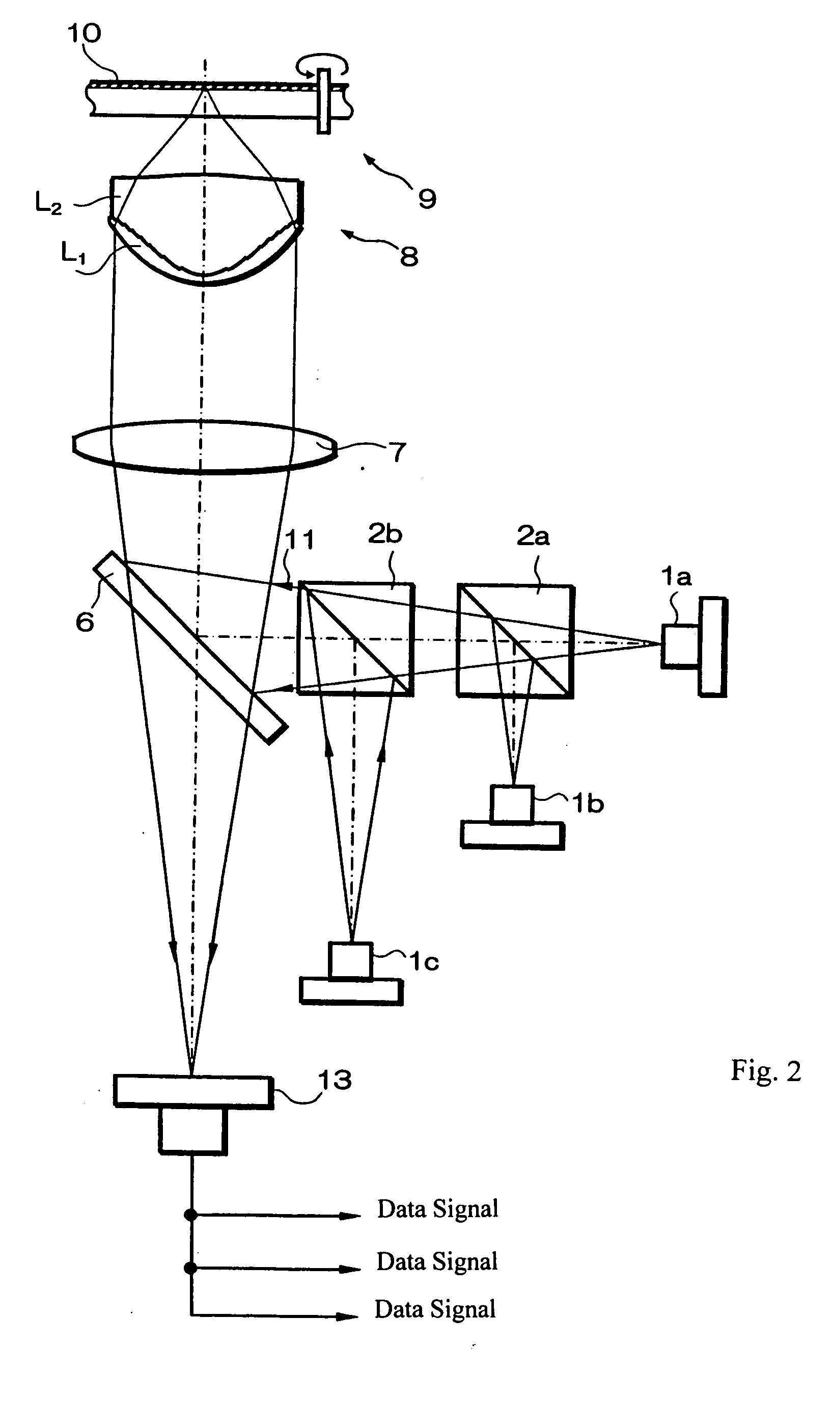
The present invention relates to an objective lens for optical recording media, wherein the objective lens includes two lens elements of different materials that are cemented together. The cemented surface of the two lens elements includes a phase function Φ, as will be discussed in detail later, which results in the cemented surface being a optical diffractive surface that enables the objective lens to focus each of three different light beams of three different wavelengths, λ1, λ2, and λ3 to a different desired position for each of first, second and third optical recording media of thicknesses, d1, d2, and d3, respectively. The optical diffractive surface is designed so that each of the three light beams is controlled favorably to a desired focus position with the three light beams all being incident on the objective lens as substantially parallel light. By enabling all three light beams to be incident as parallel light, the freedom in positioning and adjusting the positions of t...


PUM

PropertyMeasurementUnit
wavelengthaaaaaaaaaa
thicknessaaaaaaaaaa

Abstract

An objective lens consists of two lens elements of different materials that are cemented. The lens surfaces that are cemented includes a phase function so that the cemented surface forms a optical diffractive surface that enables the objective lens to focus incident light of three different wavelengths with different numerical apertures onto different optical recording media. Three conditions are satisfied so as to achieve optimum imaging. The optical diffractive surface may be shaped so that the order of the diffracted light of the shortest wavelength λ1 having the largest diffracted intensity is different from the order of the diffracted light of the second wavelength λ2 having the largest diffracted intensity, and the order of the diffracted light of the first wavelength λ1 having the largest diffracted intensity is also different from the order of the diffracted light of the third wavelength λ3 having the largest diffracted intensity.

Description

BACKGROUND OF THE INVENTION In recent years, a variety of optical recording media have been developed and optical pickup devices that carry out recording and reproducing using two alternative types of optical recording media have been known. For example, a system that carries out recording or reproducing with either a DVD (Digital Versatile Disk) or a CD (Compact Disk including CD-ROM, CD-R, CD-RW) has been used. For these two optical recording media, the DVD uses visible light having a wavelength of approximately 657 nm for improved recording densities while the CD is required to use near-infrared light having a wavelength of approximately 790 nm because there are some recording media that have no sensitivity to visible light. A single optical pickup device, known as a dual-wavelength-type pickup device, uses irradiation light of these two different wavelengths. The two optical recording media described above require different numerical apertures (NA) due to their different featur...

Claims


Application Information

Patent Timeline
Patent Type & Authority Applications(United States)
IPC IPC(8): G02B5/18G02B13/00G11B7/00G11B7/135G11B7/1353G11B7/1372G11B7/1374G11B7/1376G11B7/1392
CPCG11B7/1353G11B7/1374G11B2007/13727G11B7/13922G11B2007/0006G11B7/1376
Inventor KATSUMA, TOSHIAKIKITAHARA, YUORI, TETSUYAMORI, MASAO
Owner FUJI PHOTO OPTICAL CO LTD
Learn More