
Liquid-crystal projector

Inactive Publication Date: 2005-02-24
FUJI PHOTO OPTICAL CO LTD
View PDF5 Cites 1 Cited by
  • Summary
  • Abstract
  • Description
  • Claims
  • Application Information

AI Technical Summary

Benefits of technology

[0007] A main object of the present invention is to provide a liquid-crystal projector whose optical element is prevented from deterioration by effect of UV rays.
[0008] Another object of the present invention is to provide a liquid-crystal projector whose optical system has long lifetime.
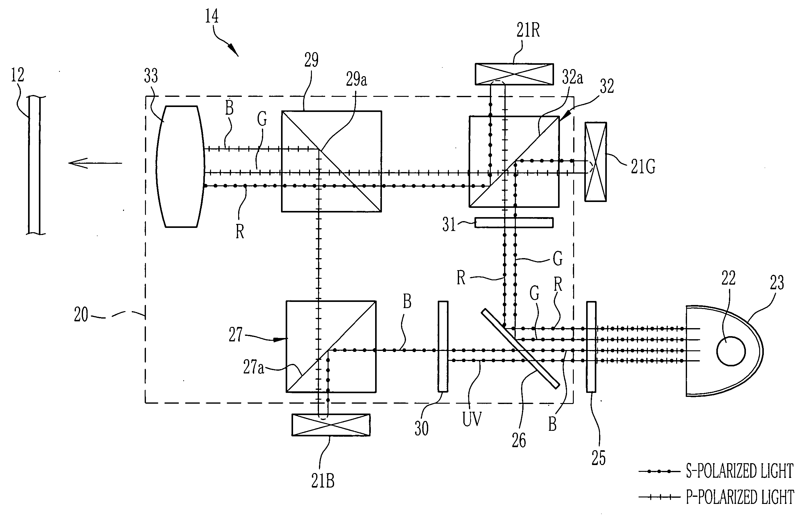
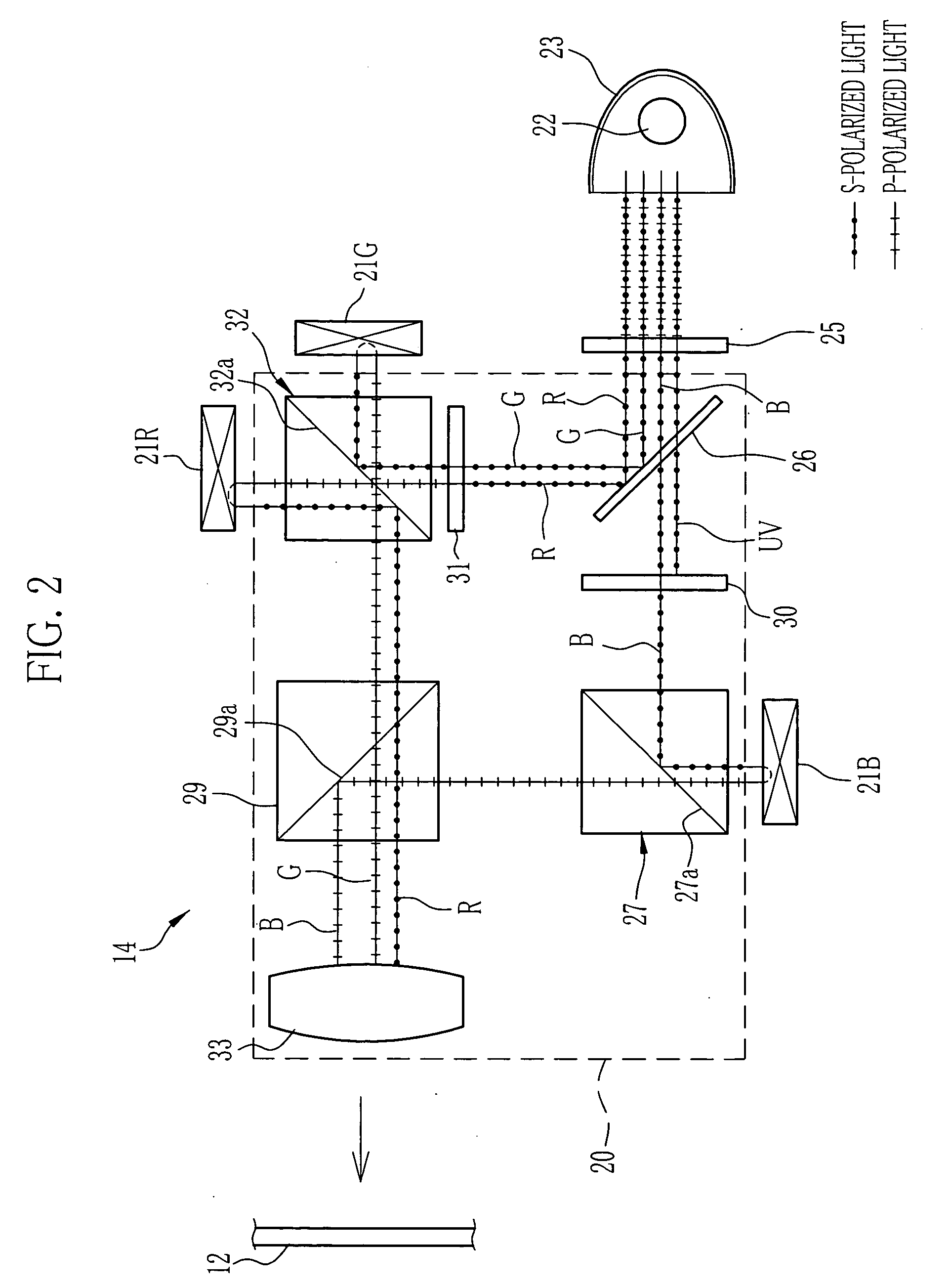
[0012] In the liquid-crystal projector of the present invention, the white light is separated into the beam containing the red and green light and the beam containing the blue light and UV rays by the first color separating means, and the UV rays are removed from the beam containing the blue light by the UV rays removing means. Accordingly, it can be reduced the deterioration of the optical components arranged in the optical path of the blue light, to lengthen the duration life of the optical system.
[0013] In the other embodiment of the present invention, the optical component which is disposed the optical path of the beam containing the blue light and the UV rays, is made of inorganic material having high resistance to the UV rays. Accordingly, it can be reduced the deterioration of the optical component.

Problems solved by technology

The polarization rotator having wavelength selectivity tends to be deteriorated by the UV rays.

Method used


Image

  • Liquid-crystal projector
  • Liquid-crystal projector
  • Liquid-crystal projector

Examples


Embodiment Construction

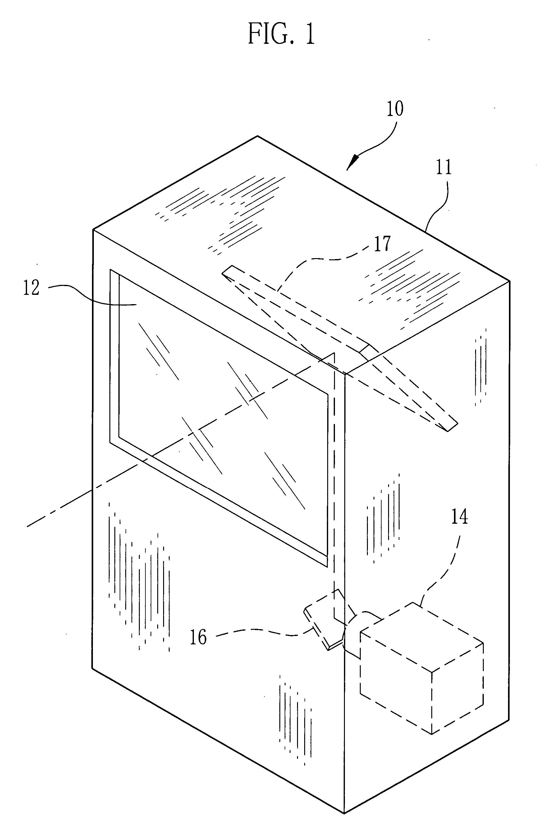
[0017] In FIG. 1, a screen 12 of diffuse transmission type is provided on front of a case 11 of a liquid-crystal projector 10. An image projected on rear side of the screen 12 is monitored from front side of the screen 12. A projection unit 14 is contained in the case 11. The image projected from the projection unit 14 is reflected by mirrors 16, 17 and focused on rear side of the screen 12. The liquid-crystal projector 10 provides a well known circuit unit including a tuner circuit and a circuit for video signal and voice signal reproduction, etc., inside the case 11. By displaying reproduction images of the video signal on liquid-crystal displays provided in the projection unit 14, the liquid-crystal projector 10 can be used for a television set having a big screen.

[0018] In FIG. 2, three reflective liquid-crystal displays 21B, 21G, 21R, which are corresponding to blue, green and red light respectively, are contained in the projection unit 14. A light source 22 emits illuminating...


PUM


Abstract

An illuminating light from a light source is separated into a beam containing red and green light and a beam containing blue light and UV rays by a dichroic mirror. The blue light is reflected by a first PBS and enters to a liquid-crystal display corresponding to the blue light. On the other hand, the beam containing the red and green light is separated into the red light and the green light by a polarization rotator and a second PBS, and the separated red and green lights enter to liquid-crystal displays corresponding to each color light. Blue, green and red image lights emitted from the respective liquid-crystal projector are composed by a composite prism. An UV cut filter is disposed between the dichroic mirror and the first PBS. The UV cut filter removes the UV rays from the optical path of the blue light, by absorbing the UV rays.

Description

BACKGROUND OF THE INVENTION [0001] 1. Field of the Invention [0002] The present invention relates to a liquid-crystal projector. More particularly, the present invention relates to a three-panel type of liquid-crystal projector having three liquid-crystal displays corresponding to red, green, and blue light respectively. [0003] 2. Description Related to the Prior Art [0004] As disclosed in Laid-Open U.S. patent application Ser. No. 2003 / 0189676, the three-panel type liquid-crystal projector having three liquid-crystal displays corresponding to the red, green, and blue color light respectively, which composes image lights modulated by each liquid-crystal displays and projects the composed image light to the screen, is well known. In this liquid-crystal projector, an illuminating light emitted from a light source is separated into the red, green, and blue lights, separeted each color lights are emitted into the corresponding liquid-crystal displays, and the image lights emitted from e...

Claims


Application Information

Patent Timeline
IPC IPC(8): G02B27/10G02F1/13G02F1/1335G03B21/00H04N9/31
CPCH04N9/3197H04N9/3105
Inventor KAWAAI, SATORU
Owner FUJI PHOTO OPTICAL CO LTD
Learn More