
Multiple sensor heat alarm

a multi-sensor, heat alarm technology, applied in the direction of electric signalling details, instruments, transportation and packaging, etc., can solve the problems of locked vehicles, limited ventilation, and interior of vehicles that may become too hot for the health of dogs

Active Publication Date: 2005-02-24
JOHN JOHNSTON +2
View PDF18 Cites 17 Cited by
  • Summary
  • Abstract
  • Description
  • Claims
  • Application Information

AI Technical Summary

Benefits of technology

[0012] A multiple heat sensor alarm system for use in a vehicle to indicate that the interior temperature is above a preset limit and has a control head with a microprocessor. Heat sensors are placed at different points in the vehicle and connected to the microprocessor which averages the sensor inputs. When the limit is exceeded the microprocessor issues an alarm command. The system is connected to the vehicle components and the alarm command operates the horn, lights (e.g. police emergency lights), sirens, fans, windows, or engine. The system may correspond to a portable beeper / pager. The microprocessor has a sophisticated time delay algorithm for use on initial start-up. The system also monitors the battery power of the vehicle and indicates a low power situation, the system sets off an alarm utilizing a power saving algorithm to enable notification to the handler before the battery power is completely exhausted.

Problems solved by technology

However, there are times during the work day when it is necessary for the officer to leave the dog in the vehicle and conduct business alone.
Usually, the vehicle is locked and ventilation is limited to prevent unintended contact between the dog and the general public.
During the summer months or other times of higher than normal temperatures, especially sunny days, the interior of the vehicle may become too hot for the health of the dog.
The conventional sensors do not always give a true reading of the ambient temperature in the vehicle and can give false warnings.
The placement of the sensor causes the inconsistent readings either because of the location of the vehicle relative to the sun or the surrounding structures.
They are not intelligent or settable.
While there are two temperature sensors, each can cause a false alarm because of their respective locations.

Method used


Image

  • Multiple sensor heat alarm
  • Multiple sensor heat alarm

Examples


Embodiment Construction

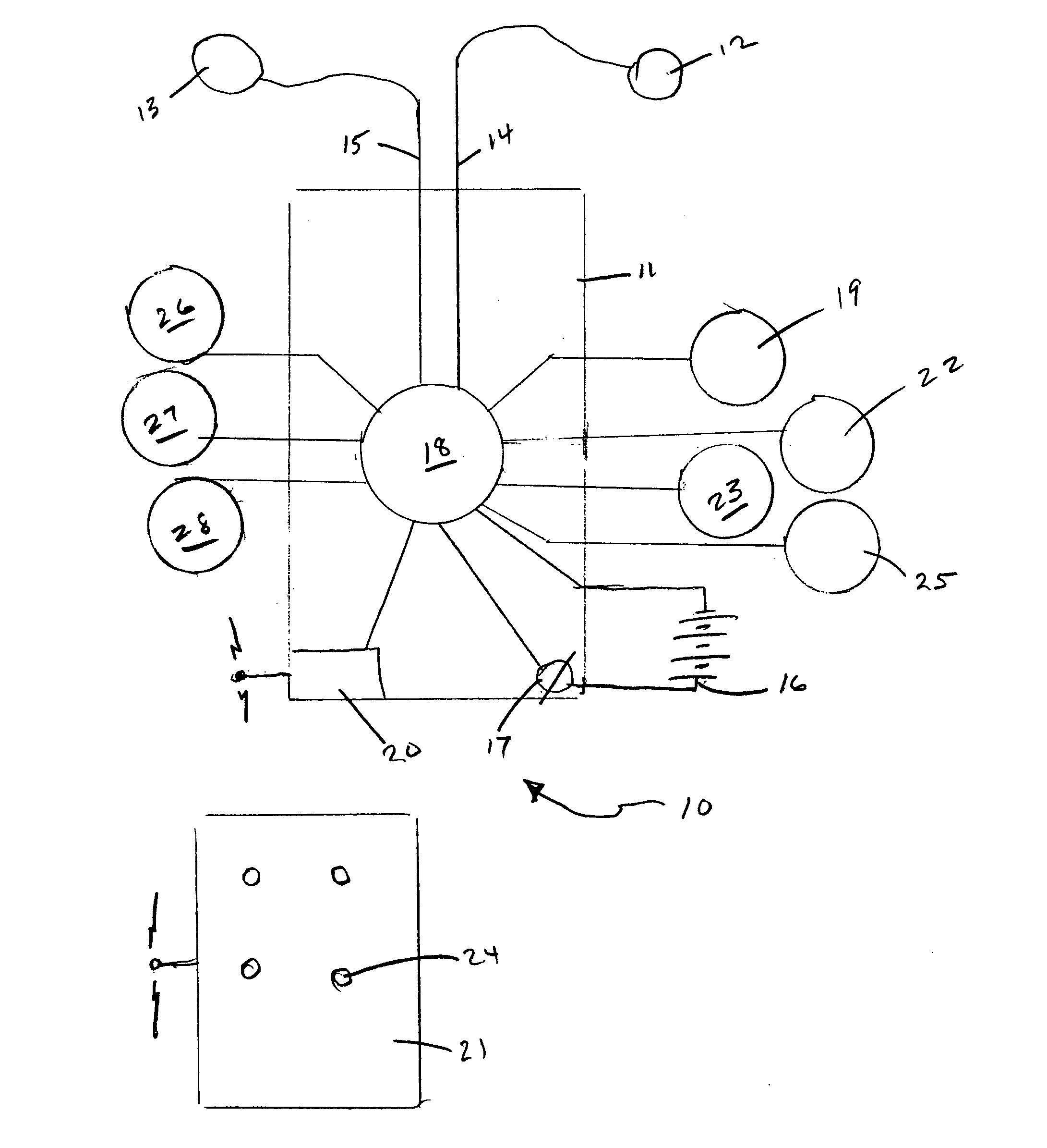
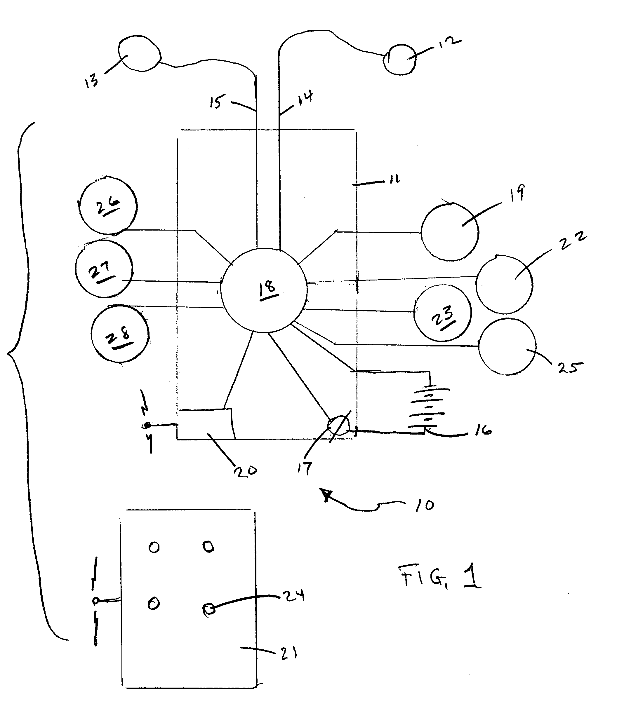
[0025] The multiple sensor heat alarm system 10 has a control head 11 and temperature sensors 12 and 13 connected by wires 14 and 15. The control head is connected to the vehicle electrical system. The circuit includes the vehicle battery 16 so that the system has power at all times. A battery pack separate from the vehicle electrical system can be used, if desired, both as an automatic back-up during periods of low vehicle battery power or to energize the system 10 totally. There is a manual ON-OFF switch 17 to disable the system and prevent draining battery power.

[0026] The system 10 has a microprocessor 18 such as, for example only, model PIC16F87X microcontroller marketed by Microchip Technology, Inc. Of course, other microprocessors may be used in the system. The microprocessor 18 is programmable and is set by the user to a desired alarm temperature threshold. The microprocessor may also be programmed to activate the different vehicle components and installed alert options to ...


PUM


Abstract

A multiple heat sensor alarm system for use in a vehicle to indicate that the interior temperature is above a preset limit has a control head with a microprocessor. Heat sensors or thermometers are placed at different points in the vehicle and connected to the microprocessor. The processor averages all sensor inputs and compares the average to the preset alarm temperature limit. When the limit is exceeded the microprocessor issues an alarm command. The system is connected to the vehicle components and the alarm command operates the horn, lights, windows, doors, or engine. The system may correspond with a portable beeper / pager. The microprocessor has a time delay mode on initial start-up. The system also monitors the battery power of the vehicle and indicates a low power situation.

Description

FIELD OF THE INVENTION [0001] This invention relates to heat alarms to protect occupants of a vehicle or other enclosed space from prolonged high ambient temperature. BACKGROUND OF THE INVENTION [0002] Law Enforcement agencies, including private / government agencies, typically have a special detachment of employees that are assigned a trained dog. These detachments are referred to as K-9 units. The care and maintenance of the K-9 is of primary importance to the officer and the department. [0003] As part of the special equipment, the K-9 unit has customized vehicles for transporting the dog along with his handler. However, there are times during the work day when it is necessary for the officer to leave the dog in the vehicle and conduct business alone. Usually, the vehicle is locked and ventilation is limited to prevent unintended contact between the dog and the general public. During the summer months or other times of higher than normal temperatures, especially sunny days, the inte...

Claims


Application Information

Patent Timeline
Patent Type & Authority Applications(United States)
IPC IPC(8): B60H1/00B60P3/04B60Q1/00G08B
CPCB60H1/00792B60P3/04B60H1/00978
Inventor JOHNSTON, JOHN
Owner JOHN JOHNSTON
Learn More