Method of releasing an attachment

a technology of releasing an attachment and a release method, which is applied in the direction of sheet joining, ropes and cables for vehicles/pulleys, shrinkage connections, etc., can solve the problems of not being able to solve the problem of poor quality, not being able to effectively disassemble a product, and being unable to meet the needs of the customer, so as to achieve efficient and cheap

Inactive Publication Date: 2005-02-17
NOKIA CORP
View PDF4 Cites 4 Cited by
  • Summary
  • Abstract
  • Description
  • Claims
  • Application Information

AI Technical Summary

Benefits of technology

[0006] An object of the present invention is to solve the above mentioned drawback and to provide an efficient and

Problems solved by technology

To manually disassemble a product is very slow and expensive.
This is, however, not a good solution because then the di

Method used


Image

  • Method of releasing an attachment
  • Method of releasing an attachment
  • Method of releasing an attachment

Examples


Embodiment Construction

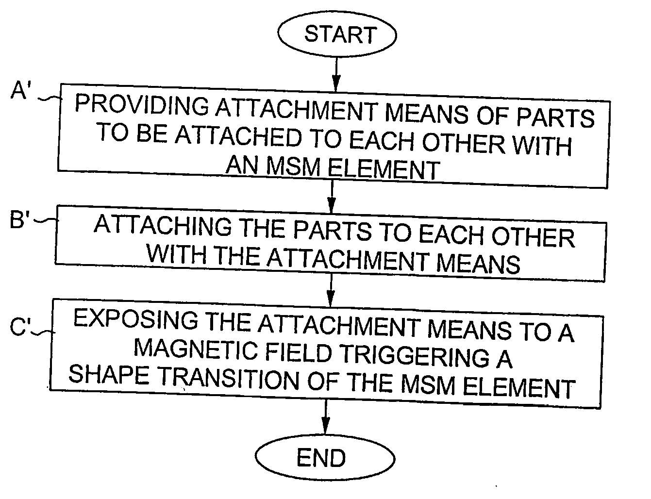
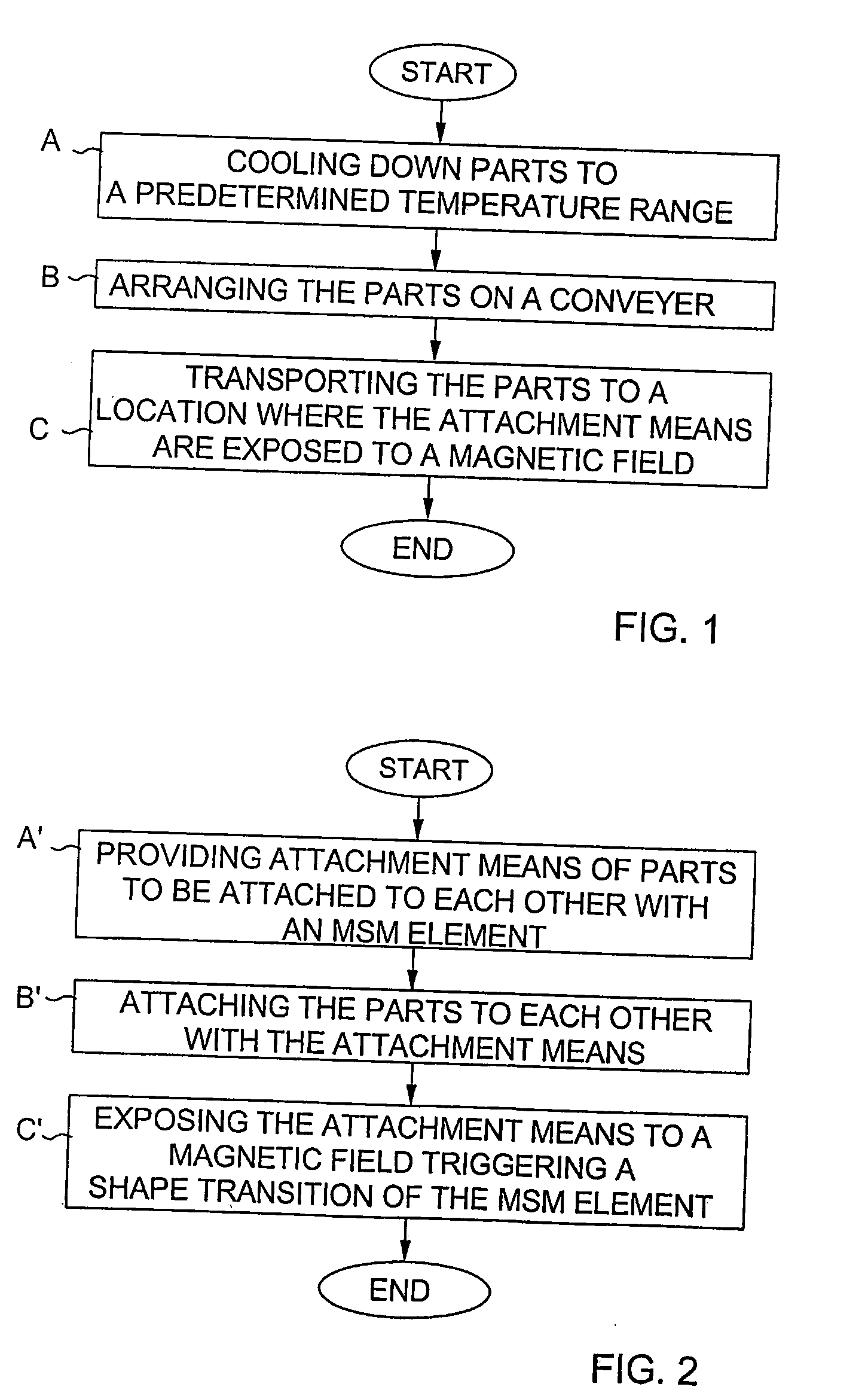
[0020]FIG. 1 is a flow diagram of a first preferred embodiment of the method of the present invention. The method of FIG. 1 can be used, for instance, for automated disassembly of mobile phones when the components of the mobile phones are to be recycled.

[0021] It is assumed in FIG. 1 that the attachment means used to attach parts to each other are provided with an MSM element. In block A the attached parts are cooled down to a predetermined temperature range dependent on the selected MSM element. In FIG. 1K is assumed, by way of example, that the MSM element is responsive to a magnetic field such that its shape changes only if the temperature of the element has been lowered to a predetermined temperature range.

[0022] The temperature range where a magnetic field can trigger the shape transition of the MSM element can be adjusted during the manufacture of the MSM element. The temperature range is effected by the consistence of the material, the manufacturing method, and heat treatme...


PUM


Abstract

The invention relates to a product comprising at least two parts (1, 2) attached to each other by at least one attachment means. In order to make automated disassembly of the product possible, said at least one attachment means (3 to 5) includes an element (5) made of an MSM material, which is shaped in a first shape allowing said at least one attachment means (3 to 5) to attach said parts (1, 2) to each other, and which is responsive to a magnetic field for entering a shape transition resulting in a second shape, whereby the attachment between said parts achieved by said at least one attachment means (3 to 5) is released.

Description

BACKGROUND OF THE INVENTION [0001] 1. Field of the Invention [0002] This invention relates to a solution which makes it possible to release an attachment between parts attached to each other. In the following the invention will be explained, by way of example, in more detail, mainly with reference to the disassembly of products whose parts shall be recycled. It is, however, important to realize that the present invention can be utilized also for other purposes. [0003] 2. Description of the Prior Art [0004] Legislation regarding the recycling of different materials has lead to a situation where more and more products need to be disassembled in order to make it possible to recycle the different parts of the products. For instance the following components must be removed from a product for recycling: Printed Wiring Boards (PWB), Liquid Crystal Displays (LCD), electrolytic capacitors, batteries, gas discharge lamps, Cathode Ray Tubes (CRT), and parts containing beryllium oxide or mercur...

Claims


Application Information

Patent Timeline
IPC IPC(8): F16B5/10F16B1/00F16B1/02F16B17/00F16B19/00H02N2/00
CPCF16B1/0014Y10T403/21F16B2001/0035F16B5/07F16B2200/77F16B2200/83
Inventor TANSKANEN, PIARYYNANEN, MATTI
Owner NOKIA CORP
Why Eureka
Try Eureka