
Method for optical coherence tomography imaging with molecular contrast

Active Publication Date: 2005-02-17
DUKE UNIV +1
View PDF4 Cites 273 Cited by
  • Summary
  • Abstract
  • Description
  • Claims
  • Application Information

AI Technical Summary

Problems solved by technology

However OCT remains a relatively contrast-starved imaging modality due to the low contrast in scattering coefficient between biological tissue types.

Method used


Image

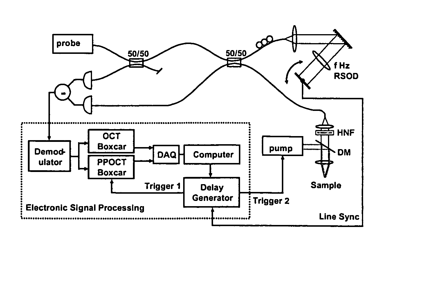
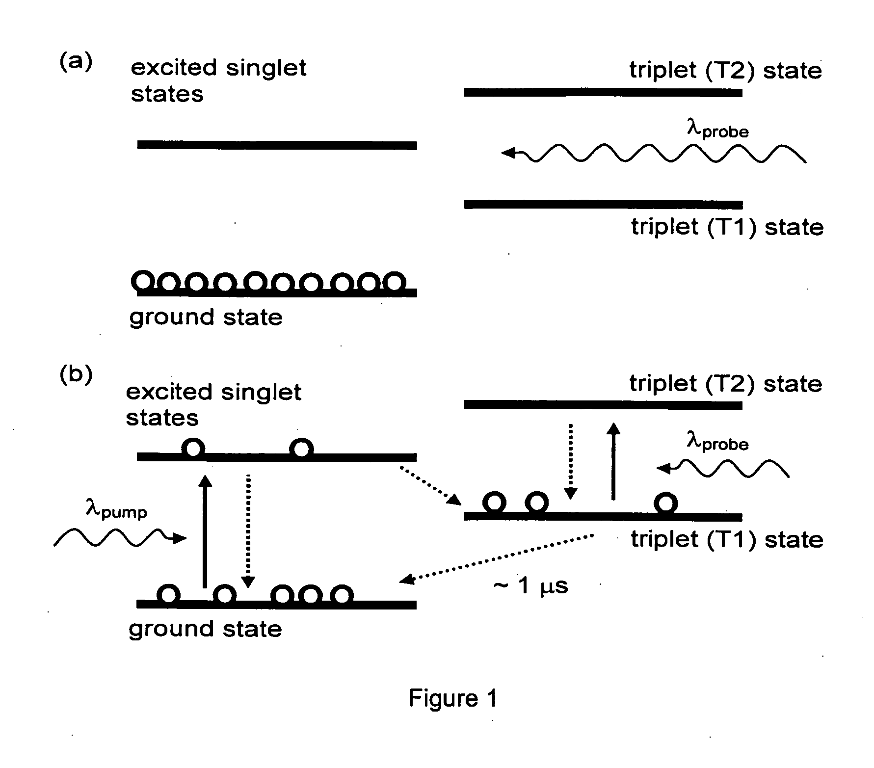
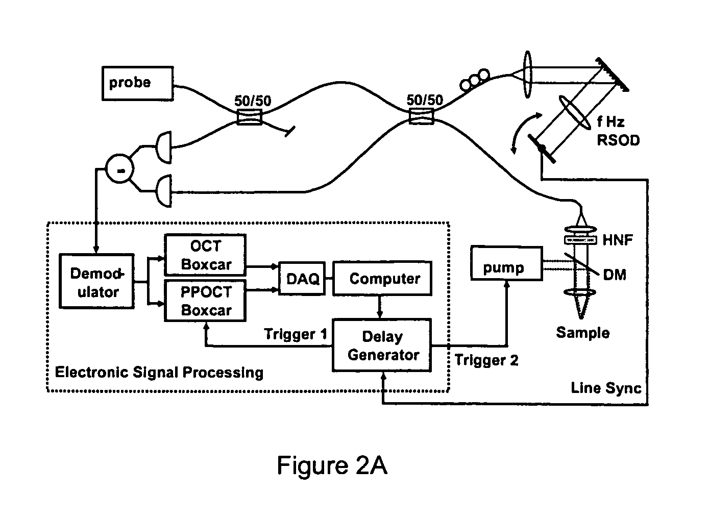
  • Method for optical coherence tomography imaging with molecular contrast
  • Method for optical coherence tomography imaging with molecular contrast
  • Method for optical coherence tomography imaging with molecular contrast

Examples


Embodiment Construction

A. Technical Overview

OCT imaging technology has not yet taken advantage of molecular contrast mechanisms which have revolutionized other medical and biological imaging modalities such as MRI, PET, and SPECT. In particular, other optical techniques such as fluorescence, confocal, and multiphoton microscopy have had tremendous impact because of their capability to image highly specific molecular targets, including antibody-conjugated fluorescent probes and genetically expressible probes such as green fluorescent protein. Unfortunately, OCT is intrinsically insensitive to incoherent scattering processes such as fluorescence or spontaneous Raman scattering, because it depends upon coherent detection of scattered light.

We have previously proposed a general concept for the use of spectroscopic OCT for detection of light from coherent inelastic scattering processes such as stimulated emission, stimulated Raman scattering, and other four-wave mixing processes (J. A. Izatt, M. D. Kulkarni...


PUM


Abstract

Spatial information, such as concentration and displacement, about a specific molecular contrast agent, may be determined by stimulating a sample containing the agent, thereby altering an optical property of the agent. A plurality of optical coherence tomography (OCT) images may be acquired, at least some of which are acquired at different stimulus intensities. The acquired images are used to profile the molecular contrast agent concentration distribution of the sample.

Description

TECHNICAL FIELD The invention relates to optical coherence tomography and, more particularly, to optical coherence tomography with molecular contrast capability. BACKGROUND ART Optical coherence tomography (OCT) is an emerging tool for real time in-situ tissue imaging with micrometer-scale resolution. Real-time OCT systems have been integrated into clinical medical diagnostic instruments, and functional extensions such as polarization-sensitive, Doppler, and spectroscopic OCT have recently been introduced. These functional enhancements add the ability to discern contrast due to stress, motion, and to some extent absorber concentration in samples such as biological tissues. However OCT remains a relatively contrast-starved imaging modality due to the low contrast in scattering coefficient between biological tissue types. DISCLOSURE OF THE INVENTION An invention is described for acquiring depth resolved optical coherence tomography (OCT) images that can reveal molecular contrast ag...

Claims


Application Information

Patent Timeline
IPC IPC(8): G01B9/02
CPCG01B9/02004G01B9/02007G01B9/02044G01B2290/70G01B9/02091G01B9/02014G01B9/02069G01B9/02002
Inventor IZATT, JOSEPH A.RAO, DIVAKAR K.YANG, CHANGHUEICHOMA, MICHAEL A.YAZDANFAR, SIAVASHROLLINS, ANDREW M.APPLEGATE, BRIAN E.
Owner DUKE UNIV
Learn More