Eureka AIR delivers breakthrough ideas for toughest innovation challenges, trusted by R&D personnel around the world.

Automatic graph display

a graph display and graph technology, applied in the field ofsignal analysis, can solve the problems of limiting the achievement of optimal utilization of the computer system, the difficulty of displaying signals, so as to facilitate automatic presentation of signal data

Active Publication Date: 2005-02-17
NATIONAL INSTRUMENTS
View PDF18 Cites 74 Cited by
  • Summary
  • Abstract
  • Description
  • Claims
  • Application Information

AI Technical Summary

Problems solved by technology

When traditional text-based programming environments are used, the user's programming skills and ability to interact with the computer system often become a limiting factor in the achievement of optimal utilization of the computer system.
There are numerous subtle complexities which a user must master before he can efficiently program a computer system in a text-based environment.
The task of programming a computer system to model or implement a process often is further complicated by the fact that a sequence of mathematical formulas, steps or other procedures customarily used to conceptually model a process often does not closely correspond to the traditional text-based programming techniques used to program a computer system to model such a process.
Since a user often is not fully proficient in techniques for programming a computer system in a text-based environment to implement his solution, the efficiency with which the computer system can be utilized often is reduced.
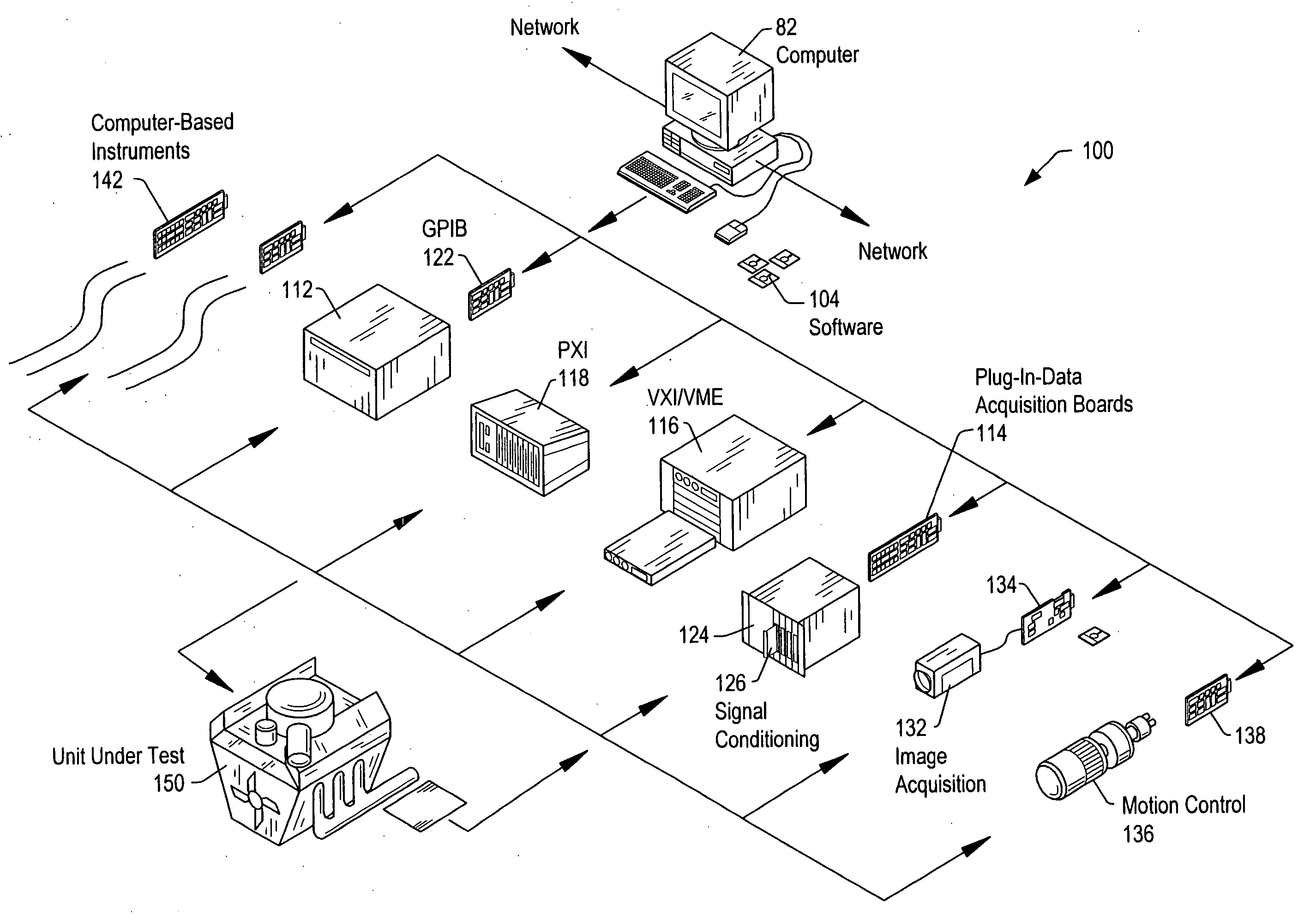
The coordinated configuration and use of these instruments to perform the desired tasks of the application generally requires significant effort, e.g., custom programming and / or coordinated configuration of the devices, and thus is often tedious, time-consuming, and error prone.
However, if one display tool of each type is already present on the screen ready for use, each display tool must be fairly small since monitor display space is limited and there is a great possibility that not all display tools will be used, as any given project may not generate all data types.
However, this approach places the burden of display tool choice on the user, and may result in errors, e.g., the user requesting an incompatible display tool by mistake or due to lack of knowledge.

Method used


Image

  • Automatic graph display
  • Automatic graph display
  • Automatic graph display

Examples


Embodiment Construction

Incorporation by Reference

The following references are hereby incorporated by reference in their entirety as though fully and completely set forth herein:

U.S. provisional application Ser. No. 60 / 495,478, titled “Mixed Signal Workbench”, filed Aug. 15, 2003.

U.S. provisional application Ser. No. 60 / 496,318, titled “A Mixed Signal Analysis System and Method of Use”, filed Aug. 19, 2003.

U.S. Pat. No. 4,914,568 titled “Graphical System for Modeling a Process and Associated Method,” issued on Apr. 3, 1990.

U.S. Pat. No. 5,481,741 titled “Method and Apparatus for Providing Attribute Nodes in a Graphical Data Flow Environment”.

U.S. Pat. No. 6,173,438 titled “Embedded Graphical Programming System” filed Aug. 18, 1997.

U.S. Pat. No. 6,219,628 titled “System and Method for Configuring an Instrument to Perform Measurement Functions Utilizing Conversion of Graphical Programs into Hardware Implementations,” filed Aug. 18, 1997.

U.S. Patent Application Publication No. 20010020291 (Se...


PUM


Abstract

System and method for displaying signals. First user input requesting display of a first signal is received, e.g., to a graphical user interface (GUI) comprised in a signal analysis function development environment, and the first signal programmatically analyzed in response to the first user input. A display tool operable to display the first signal is programmatically determined based on said analyzing, and the first signal displayed in the display tool, e.g., a data type of the first signal is determined, e.g., integer, floating point, Boolean, or user-defined data in a time-domain, frequency-domain, or spatial-domain, and the display tool programmatically determined based on the determined data type, e.g., via a loop-up table, where the display tool comprises an indicator operable to display the signal data. The signal comprises signal data, e.g., signal plot data, where the display tool comprises a graph, or tabular data, where the display tool comprises a table.

Description

FIELD OF THE INVENTION The present invention relates to the field of signal analysis, and more particularly to a system and method for interactively specifying and performing signal analysis functions. DESCRIPTION OF THE RELATED ART Traditionally, high level text-based programming languages have been used by programmers in writing application programs. Many different high level text-based programming languages exist, including BASIC, C, C++, Java, FORTRAN, Pascal, COBOL, ADA, APL, etc. Programs written in these high level text-based languages are translated to the machine language level by translators known as compilers or interpreters. The high level text-based programming languages in this level, as well as the assembly language level, are referred to herein as text-based programming environments. Increasingly, computers are required to be used and programmed by those who are not highly trained in computer programming techniques. When traditional text-based programming environm...

Claims


Application Information

Patent Timeline
Patent Type & Authority Applications(United States)
IPC IPC(8): G06F3/033G06F3/048G06F9/44G06T1/00G06T11/20
CPCG06F8/34G06F3/0486G06F11/2273Y10S715/964Y10S715/97
Inventor JOFFRAIN, PHILIPPE G.CIFRA, CHRISTOPHER G.MORIAT, ALAIN G.RESTAT, CHRISTOPHE A.PASQUARETTE, JOHN A.FLETCHER, J. CLINTON
Owner NATIONAL INSTRUMENTS
Why Eureka
Eureka Blog
Learn More