
Construction for connecting a circuit board and an electrical part, a brake oil pressure control unit

a technology of brake oil pressure control unit and construction method, which is applied in the direction of coupling device connection, braking system, instruments, etc., can solve the problems of difficult detachment of two electronic control units, high cost, and abnormalities in one electronic control unit, so as to achieve easy detachment operation

Active Publication Date: 2005-02-10
SUMITOMO WIRING SYST LTD
View PDF10 Cites 49 Cited by
  • Summary
  • Abstract
  • Description
  • Claims
  • Application Information

AI Technical Summary

Benefits of technology

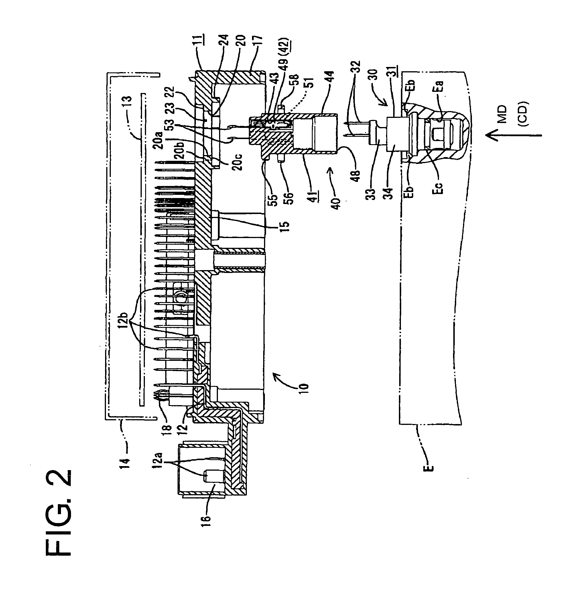
[0008] The invention relates to a construction for electrically connecting a circuit board in a first unit box and an electrical part in a second unit box as the first and second unit boxes are assembled. An intermediate connector is provided in the first unit box and has at least one terminal fitting with a first portion inseparably connectable with the circuit board and a second portion separably connectable with a terminal of the electrical part. Thus, the connected state of the terminal fitting and the circuit board need not be canceled upon detaching the two unit boxes, and the detaching operation can be performed easily performed.
[0009] The two unit boxes may be displaced in a direction intersecting the assembling direction during assembly of the two unit boxes. Accordingly, the intermediate connector preferably is mounted in the first unit box via a displacement take-up means for resiliently displacing the intermediate connector relative to the first unit box in a direction intersecting the assembling direction of the two unit boxes. The displacement take-up means enables the intermediate connector to be displaced relative to the first unit box in the direction intersecting the assembling direction, thereby taking up the displacement of the two unit boxes. Thus, the terminal of the electrical part can be connected smoothly with the terminal fitting of the intermediate connector.

Problems solved by technology

An abnormality may occur in one of the electronic control units.
However, the terminals 3a of the pressure sensor 3 are soldered to the printed circuit board 4, and it difficult to detach the two electronic control units 1, 2.
Thus, both electronic control units 1, 2 need to be exchanged, which leads to a higher cost.

Method used


Image

  • Construction for connecting a circuit board and an electrical part, a brake oil pressure control unit
  • Construction for connecting a circuit board and an electrical part, a brake oil pressure control unit
  • Construction for connecting a circuit board and an electrical part, a brake oil pressure control unit

Examples


Embodiment Construction

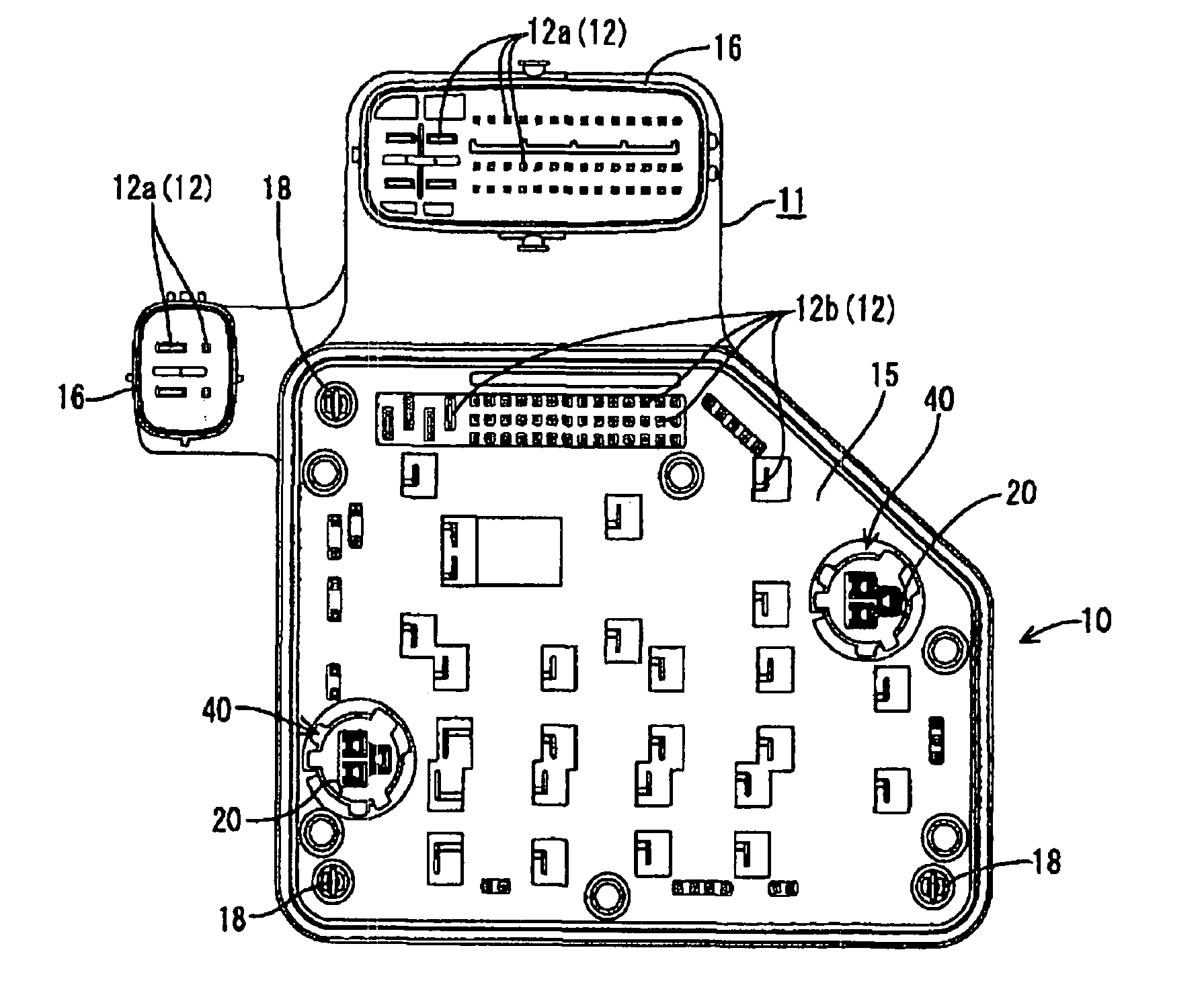
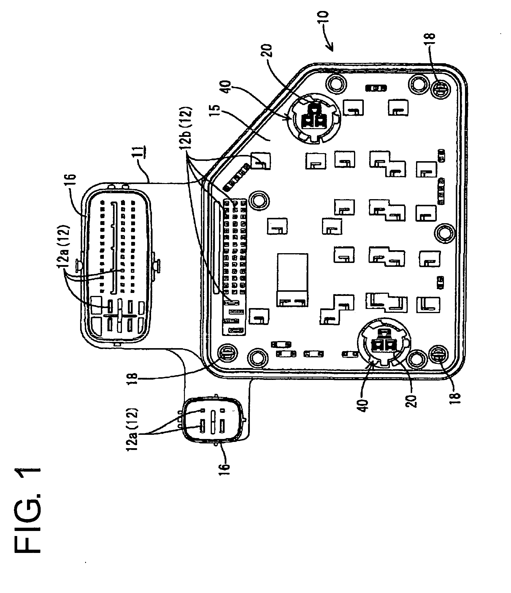
[0042] A first embodiment of the invention is described with reference to FIGS. 1 to 10. The first embodiment shows a brake oil pressure control unit which is an integral or unitary assembly of two electronic control units 10, E and to be installed in an automotive vehicle. In the following description, reference is made to FIG. 2 and other figures concerning vertical direction.

[0043] As shown in FIGS. 1 and 2, the first electronic control unit 10 is comprised of a unit main body 11 having busbars 12 built therein, an electronic circuit comprising a printed circuit board 13 to be mounted on the upper surface of the unit main body 11, and a cover 14 to be put on the upper surface of the unit main body 11 to at least partly cover the printed circuit board 13.

[0044] The unit main body 11 has busbars 12 embedded at least partly one over another in a resin member, and includes a board mounting portion 15 on which the printed circuit board 13 and the cover 14 are to be mounted. The unit...


PUM


Abstract

A first electronic control unit (10) provided with a printed circuit board (13) and a second electronic control unit (E) having pressure sensors (30) mounted therein can be assembled with each other. Intermediate connectors (40) are mounted in the first electronic control unit (10), and terminal fittings (42) are accommodated therein. Each terminal fitting (42) is provided with a board-side connecting portion (53) to be soldered to the printed circuit board (13) and a resilient contact piece (51) to be resiliently brought into contact with a terminal portion (32) of the pressure sensor (30).

Description

BACKGROUND OF THE INVENTION [0001] 1. Field of the Invention [0002] The invention relates to a construction for connecting a circuit board and an electrical part, to a brake oil pressure control unit and to a method of connecting a circuit board and an electrical part. [0003] 2. Description of the Related Art [0004] Electronic control units normally are installed separately in an automotive vehicle. However, consideration has been given to assembling two electronic control units into an integral unit to achieve miniaturization. Some electronic control units are designed to precisely control oil pressure and have a pressure sensor for detecting oil pressure during a brake oil pressure control. In such a case, there is an increasing necessity to connect the pressure sensor with a printed circuit board accommodated in a mating electronic control unit as two electronic control units are assembled into an integral unit. To this end, as diagrammatically shown in FIG. 19, terminals 3a of a...

Claims


Application Information

Patent Timeline
IPC IPC(8): H01R12/00B60T8/34H01R13/631H01R13/73H01R13/74
CPCB60T8/3675F15B13/0857F15B13/086G01L19/003H01R2201/26G01L19/148H01R9/226H01R13/6315H01R13/743G01L19/0061
Inventor TAKANASHI, HITOSHITSUNOOKA, TAKAOSEKIHARA, YASUHITO
Owner SUMITOMO WIRING SYST LTD
Learn More