
Climbing device

a technology of climbing device and locking mechanism, which is applied in the field of climbing device, can solve the problems of steel workers located construction personnel in potentially hazardous locations, slow and tedious process, etc., and achieves the effect of simple and reliable locking mechanism and preventing the disengagement of the climbing devi

Inactive Publication Date: 2005-02-10
LOU DONE
View PDF14 Cites 2 Cited by
  • Summary
  • Abstract
  • Description
  • Claims
  • Application Information

AI Technical Summary

Benefits of technology

[0009] This need is met by a climbing device configured to have a lever-actuating assembly, operating the climbing device so as to engage an I-beam, and a locking mechanism preventing displacement of the lever-actuating assembly in its desired position relative to the I-beam. The climbing device is utilized to provide a foothold to the user, and a means to attach the user, through a tether arrangement, to the structure to reduce the possibility of a fall through an accidental slippage.
[0010] In one aspect, the lever-actuating assembly includes a handle and a footplate components, which are connected to a piston configured to engage and secure the I-beam so that rotation of these components relative one another causes the piston to move linearly between its engaging and locked positions. In contrast to many known functionally similar devices requiring a combination of external linkages, which connect the piston to at least one of the components, the invention provides for direct connection between the piston and the components, thus, avoiding additional cost-inefficient parts and a complicated structure. In fact, since the space at a construction site is limited, the inventive device is advantageously distinguished from the known devices since its structure is compact.
[0012] It is therefore an object of the invention to provide a climbing device attachable to a structure in a reliable manner.
[0013] A further object of the invention is to provide a climbing device configured to have a simple and reliable locking mechanism preventing disengagement of the climbing device from the engaged structure upon loading of the inventive device.
[0014] Still another object of the invention is to provide a climbing device with a locking mechanism releasable in response to the force generated by the user in a simple manner allowing the user to change his / her position by reengaging the climbing device to another support in a time-efficient manner.
[0015] Another object of the invention is to provide a climbing device characterized by a structure that can be easily serviced to maintain the originally assembly parts as well as to replace those with new parts, if a need exists.

Problems solved by technology

The construction of large steel structures, such as office buildings, bridges, apartment dwellings, and other large multi-story buildings, often times place construction personnel in potentially hazardous locations during both the construction of the building and after its completion, typically during maintenance and general upkeep of the structure.
The steel workers are typically located in potentially hazardous locations, in that there is no flooring or secure footing in place until the I-beams are actually bolted into place.
This makes for a slow and tedious process; each time the worker moves from beam to beam, he must disconnect himself, unwrap the tether from the column or beam, and move to the next location.
A further disadvantage of the existing methods for constructing building frames lies in the fact that most I-beams upon which workers are expected to stand are typically between 8″ and 24″ wide.
This slows the construction process, and consequently increases the cost of both the construction of the building, and its related costs such as insurance premiums.
With the modern building structures becoming more and more tall and complex, the demands to the safety of steel workers also rise.
Some of the newly developed safety requirements may not be fully met by known devices.

Method used


Image

  • Climbing device
  • Climbing device
  • Climbing device

Examples


Embodiment Construction

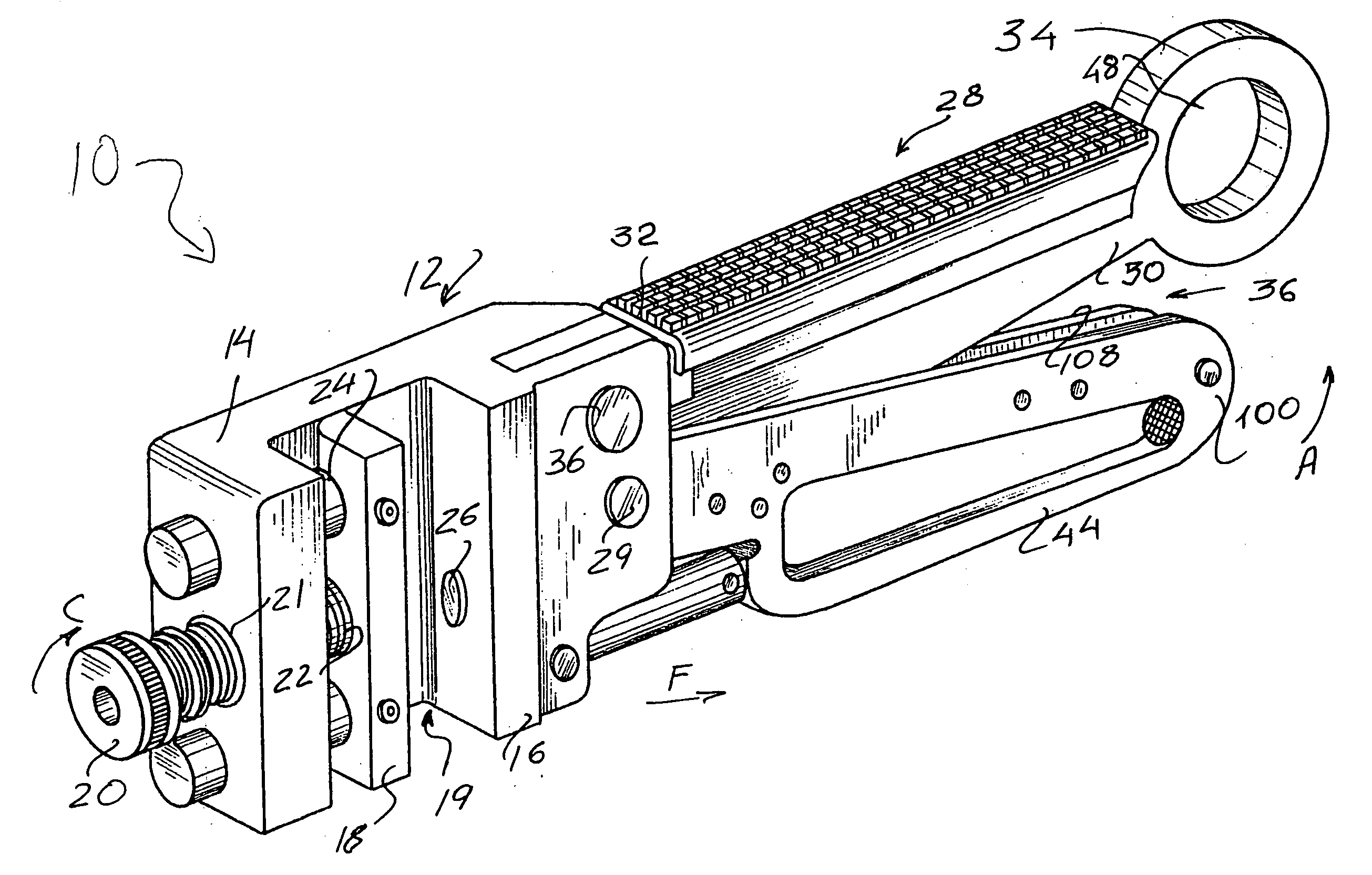
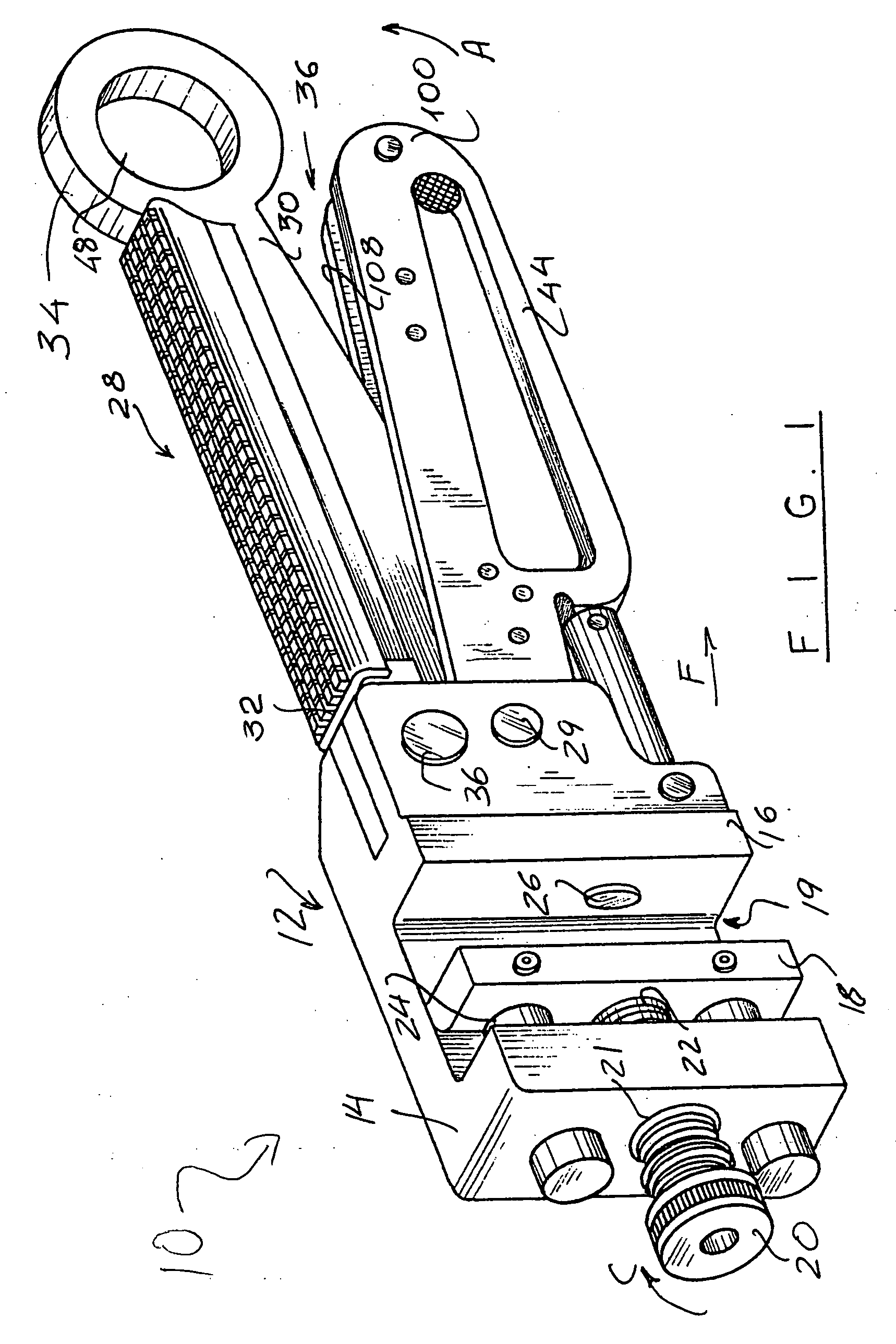
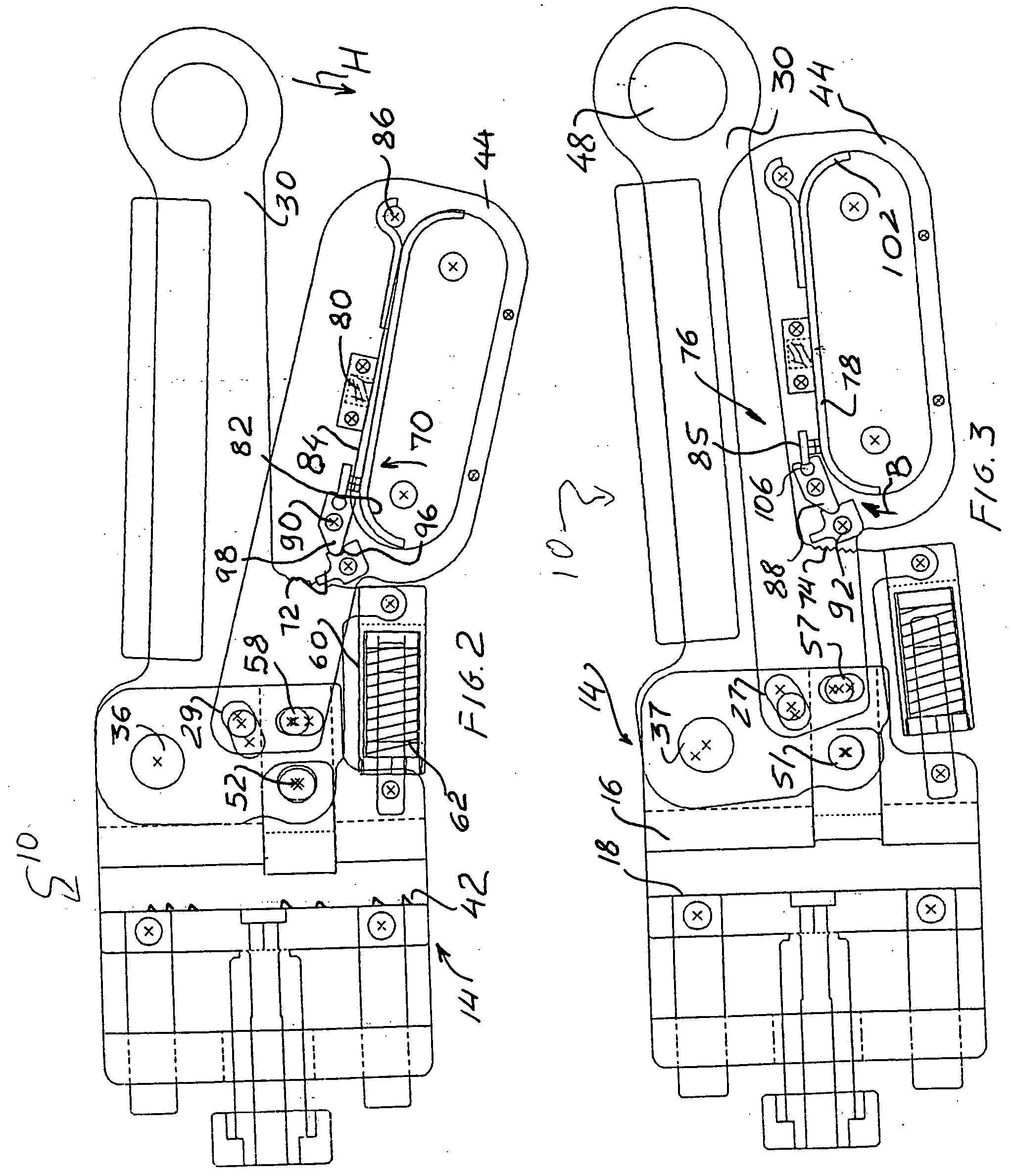
[0020] Turning now to the drawings, in which like reference numerals identify similar or identical elements throughout the several views, the climbing device 10 of the present invention is illustrated in FIG. 1. Device 10 is preferably constructed of a metal material such as steel in order to support the weight of a person using the device and to prevent damage to the device during use. However, other suitable materials having a high impact strength or hardness may be utilized.

[0021] Climbing device 10, as seen in FIG. 1, includes a jaw assembly 12 constructed of a “U” shaped frame 14 in which one of the legs defines a first stationary jaw 16 while the other jaw 18 is operative to move relative to the first jaw 16. Except for the movable jaw, the frame 14 may be assembled of multiple parts, but preferably, in order to increase its resistance to bending loads, the frame is configured as a one-piece structure. Movable jaw 18 may be displaced to adjust a spacing 19 between the jaws 16...


PUM


Abstract

A climbing device is configured to have a locking mechanism operative to allow the handle and the footplate of the climbing device to pivot to and engage a portion of building structure in a position, in which further displacement of the footplate and handle relative to one another is arrested to lock the portion between the jaws of the device.

Description

BACKGROUND OF THE INVENTION [0001] 1. Field of the Invention [0002] The present invention relates to devices attachable to frames of structures such as buildings, towers, bridges, and the like both during and after the construction of the structure. In particular, the invention relates to a climbing device removably attachable to a beam, girder or column of the building frame, such as an I-beam, to provide secure footing or secure attachment for construction personnel to the frame while working on the building. [0003] 2. Discussion of the Prior Art [0004] The construction of large steel structures, such as office buildings, bridges, apartment dwellings, and other large multi-story buildings, often times place construction personnel in potentially hazardous locations during both the construction of the building and after its completion, typically during maintenance and general upkeep of the structure. Typically, during construction, after the foundation is laid the building frame is ...

Claims


Application Information

Patent Timeline
IPC IPC(8): A62B1/04A63B29/02E04G3/00E06C9/00
CPCA63B29/02A62B35/0068
Inventor COWIN, LOUIS J.
Owner LOU DONE
Learn More