
Methods and compositions of a storable relatively lightweight proppant slurry for hydraulic fracturing and gravel packing applications

a technology of hydraulic fracturing and gravel packing, which is applied in the direction of fluid removal, chemistry apparatus and processes, borehole/well accessories, etc., can solve the problems of proppant pack and/or formation damage, interference with proper placement downhole, and formation damage. , to achieve the effect of improving the overall system performan

Inactive Publication Date: 2005-02-10
BAKER HUGHES INC
View PDF99 Cites 195 Cited by
  • Summary
  • Abstract
  • Description
  • Claims
  • Application Information

AI Technical Summary

Benefits of technology

In the disclosed method, the application of relatively lightweight and / or substantially neutrally buoyant particulate material as a fracture proppant particulate advantageously may provide for substantially improved overall system performance in hydraulic fracturing applications, or in other well treating applications such as sand control.
In one embodiment, the disclosed relatively lightweight particulate may be introduced or pumped into a well as neutrally buoyant particles in, for example, a saturated sodium chloride solution carrier fluid or a carrier fluid that is any other completion or workover brine known in the art, for example, having an ASG of from about 1 to about 1.5, alternatively from about 1.2 to about 1.5, further alternatively about 1.2, thus eliminating the need for damaging polymer or fluid loss material. In one embodiment, such a material may be employed as proppant / sand control particulate material at temperatures up to about 150° F., and pressures up to about 1500 psi. However, these ranges of temperature and closure stress are exemplary only, it being understood that the disclosed materials may be employed as proppant / sand control materials at temperatures greater than about 1 50° F. and / or at closure stresses greater than about 1500 psi. For example, particles of naturally occurring material may be exposed to suitable modifying agents, with or without enhancing agents and / or conditions, in one embodiment to form relatively lightweight particulate materials that may be employed as proppant or sand control particulate at temperatures up to about 300° F., and / or at closure stresses up to about 10,000 psi, with temperatures greater than about 300° F. and / or closure stresses greater than about 10,000 psi also being possible. In any event, it will be understood with benefit of this disclosure that core and / or layer material / s (when present) and / or interaction-enhancing materials / conditions may be selected by those of skill in the art to meet and withstand anticipated downhole conditions of a given application.

Problems solved by technology

Gelling agents for proppant carrier fluids may provide a source of proppant pack and / or formation damage, and settling of proppant may interfere with proper placement downhole.
Formation damage may also be caused by gelled carrier fluids used to place particulates downhole for purposes such as for sand control, e.g., gravel packs, frac packs, etc.
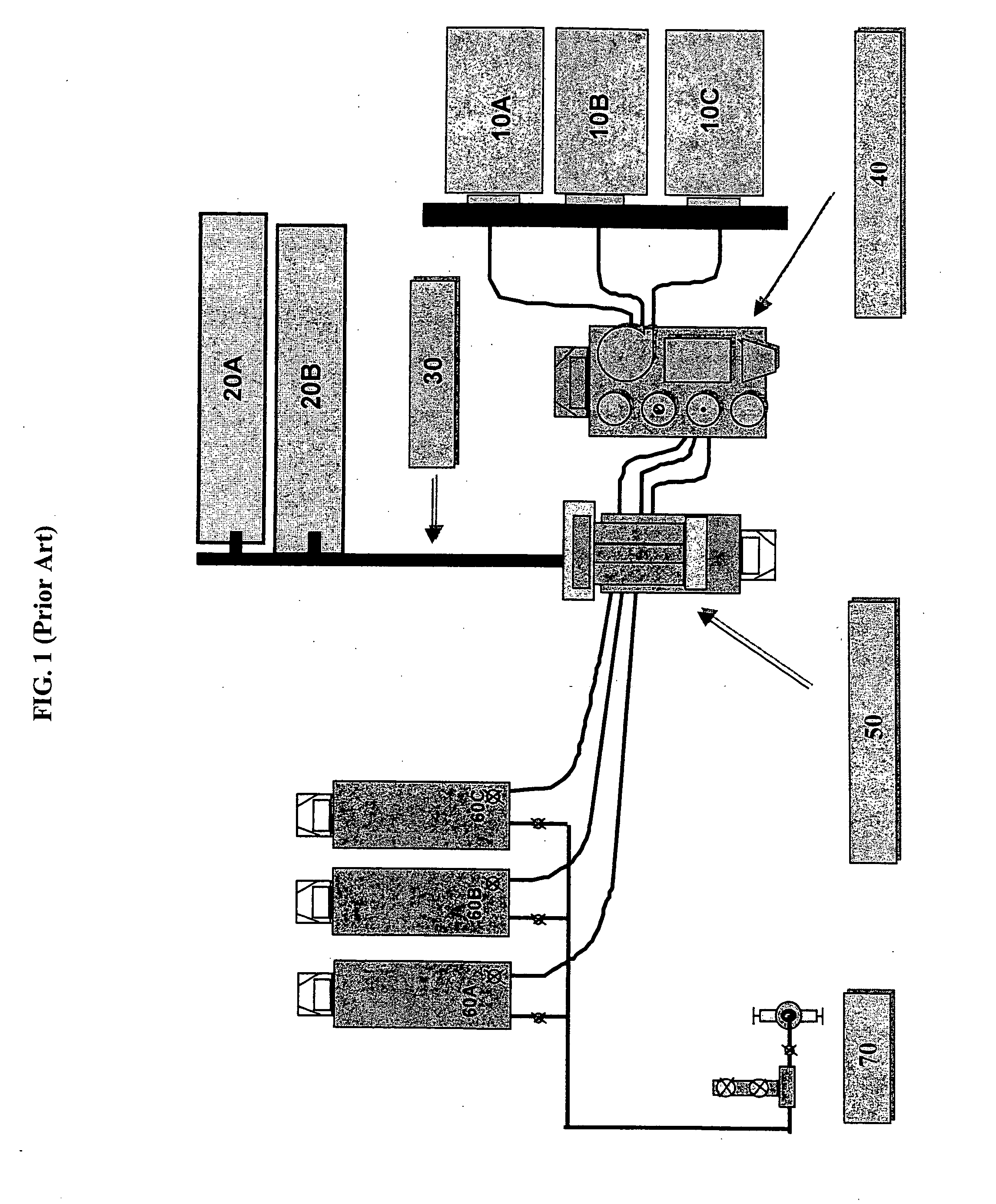
At the time of proppant addition, the carrier fluid exhibits poor solid suspending properties and vigorous agitation is required to prevent gravity segregation of the solids.
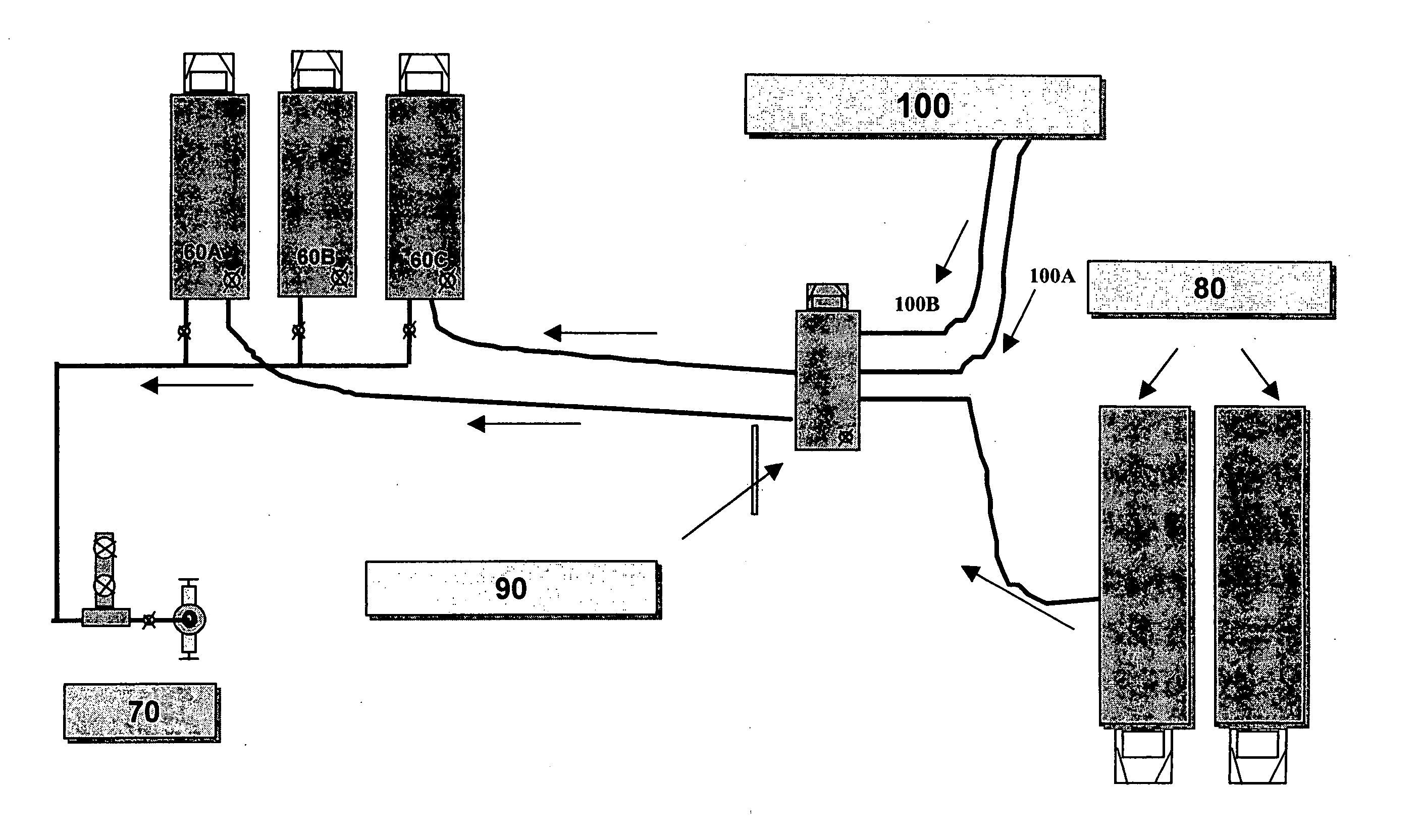
The operation of combining the proppant with the fluid involves the use of slurry blender 50, a relatively sophisticated and costly piece of equipment.
Any operational failure, such as tub overflow, improper amount of viscosity enhancer, breaker, etc., jeopardizes the operation or its results.
Unfortunately, such formulations require a high degree of fluid gellation to maintain suspension of the heavy particles.
Even with heavy gellation, such suspensions are further subject to particle settling within a matter of hours, particularly in the presence of vibration.
Significant costs are further incurred for the chemicals, equipment and processing time in order to gel the carrier fluid.

Method used


Image

  • Methods and compositions of a storable relatively lightweight proppant slurry for hydraulic fracturing and gravel packing applications
  • Methods and compositions of a storable relatively lightweight proppant slurry for hydraulic fracturing and gravel packing applications
  • Methods and compositions of a storable relatively lightweight proppant slurry for hydraulic fracturing and gravel packing applications

Examples


example 1

Conductivity tests were performed according to API RP 61 (1st Revision, Oct. 1, 1989) using an API conductivity cell with Ohio sandstone wafer side inserts. Each particulate material sample was loaded into the cell and closure stress applied to the particulate material using a “DAKE” hydraulic press having a “ROSEMOUNT” differential transducer (#3051C) and controlled by a “CAMILE” controller. Also employed in the testing was a “CONSTAMETRIC 3200” constant rate pump which was used to flow deionized water through each particulate sample.

The coated ground walnut particulate material employed was ground walnut hulls from “COMPOSITION MATERIALS, INC.” having a size of about 12 / 20 mesh and having an in situ Young's modulus of from about 1,000,000 psi to about 2,000,000 psi. The ground walnut particulate material was coated with a layer of BORDEN “SIGMASET LV” low volatility resin in an amount of about 12% by weight of total particulate weight, and the particles were manufactured by “BO...

example 2

Using a procedure similar to that of Example 1, the same type of 12 / 20 mesh ground walnut hull core material was tested with different types of resin layers from BORDEN. Testing was carried out for all samples at 150° F. and closure stresses ranging from 500 psi to 2000 psi. For two of samples, testing was also carried out at 200° F. and closure stress of 2200 psi. Resin type and amounts used in each sample are identified in Table IV. Results of this testing is given in Tables V and VI, and in FIGS. 5 and 6.

TABLE IVBORDEN Resin Layers on 12 / 20 MeshGround Walnut Shell MaterialLayer Type and Amount (%by Weight of Total WeightSample Identifierof Particle)*AInner layer of 2% by weightBORDEN “2AC” with OuterLayer of 4% by weightBORDEN “SIGMASET LV”BLayer of 6% by weightBORDEN “SIGMASET LV”resin (Coated particles havingBorden identification code“66040”)CLayer of 6% by weightBORDEN “SIGMASET LV”resin (Coated particles havingBorden identification code“66535”)DBORDEN Two Coat Resin —Inner...

example 3

Using a procedure similar to that of Example 1, conductivity tests were performed on three different samples of 12 / 20 mesh ground walnut shells at 150° F. and at a concentration of 1 lb / ft2: Sample A (treated with inner layer of phenol formaldehyde resin and outer layer of urethane epoxy resin); Sample B (soaked for 4 hours at room temperature in FSA-1 siloxane-based compound); and Sample C (spray treated with FSA-1 in an amount of 26% by weight of the ground walnut hull material). The particles of Samples A and C were manufactured by FRITZ, while the particles of Sample B were manufactured in the laboratory. Results of this testing is shown in Table VII and FIG. 7.

TABLE VIIPermeability, DarciesClosureStress, psiSample ASample BSample C10009124025020008617012030003010080

FIG. 7 shows the permeability of the ground walnut hull materials of the three samples of this example at 500, 1000 and 2000 psi closure stresses and 150° F.

The results of this example illustrate how ground waln...


PUM


Abstract

Methods and compositions useful for subterranean formation treatments, such as hydraulic fracturing treatments and sand control that utilize relatively lightweight and / or substantially neutrally buoyant particulates. Particles that may be employed include particulates of naturally occurring materials that may be optionally strengthened or hardened by exposure to a modifying agent; porous materials including selectively configured porous material particles manufactured and / or treated with selected glazing materials, coating materials and / or penetrating materials; and well treating aggregates composed of an organic lightweight material and a weight modifying agent. The relatively lightweight particulate may be suspended as a substantially neutral buoyant particulate and stored with a carrier fluid as a pumpable slurry.

Description

FIELD OF THE INVENTION This invention relates generally to methods and compositions useful for subterranean formation treatments, such as hydraulic fracturing treatments and sand control. In particular, this invention relates to use of relatively lightweight and / or substantially neutrally buoyant particles as proppant material in hydraulic fracturing treatments and as particulate material in sand control methods such as gravel packing, frac pack treatments, etc. In addition, this invention relates to a storable pumpable proppant suspension containing the relatively lightweight proppant particles. BACKGROUND OF THE INVENTION Hydraulic fracturing is a common stimulation technique used to enhance production of fluids from subterranean formations. In a typical hydraulic fracturing treatment, fracturing treatment fluid containing a solid proppant material is injected into the wellbore at high pressures. Once natural reservoir pressures are exceeded, the fluid induces fractures in the f...

Claims


Application Information

Patent Timeline
IPC IPC(8): C09K8/62C09K8/68C09K8/80E21B43/267
CPCC09K8/62C09K8/68E21B43/267C09K8/80C09K8/805C09K8/685
Inventor BRANNON, HAROLD DEANWOOD, WILLIAM DALERICKARDS, ALLAN RAYSTEPHENSON, CHRISTOPHER JOHN
Owner BAKER HUGHES INC
Learn More