
Transmitting device, receiving device and transmitting/receiving system

Inactive Publication Date: 2005-02-03
PANASONIC CORP
View PDF10 Cites 54 Cited by
  • Summary
  • Abstract
  • Description
  • Claims
  • Application Information

AI Technical Summary

Benefits of technology

[0029] With the above-described known transmitting / receiving system, a video signal recorded on a recording medium can be reproduced by a display device. However, rapid progress in AV equipment has been made in recent years, and thus technology for achieving further improvement of display quality, reduction in price and the like has been always required.
[0030] As for the known transmitting / receiving system, in the configuration of FIG. 4, not only a port with which the transmission controller 142 controls the low-speed bus 162 but also another port has to be prepared. This increases the size of the transmission controller 142 and also costs are increased.

Problems solved by technology

This increases the size of the transmission controller 142 and also costs are increased.
Accordingly, if the length of the transmission line 160 is increased, a problem arises in which waveform distortion is generated and information can not be transmitted.
Thus, a capacity load is large.
This also has made difficult to increase the length of the transmission line 160.

Method used


Image

  • Transmitting device, receiving device and transmitting/receiving system
  • Transmitting device, receiving device and transmitting/receiving system
  • Transmitting device, receiving device and transmitting/receiving system

Examples


first embodiment

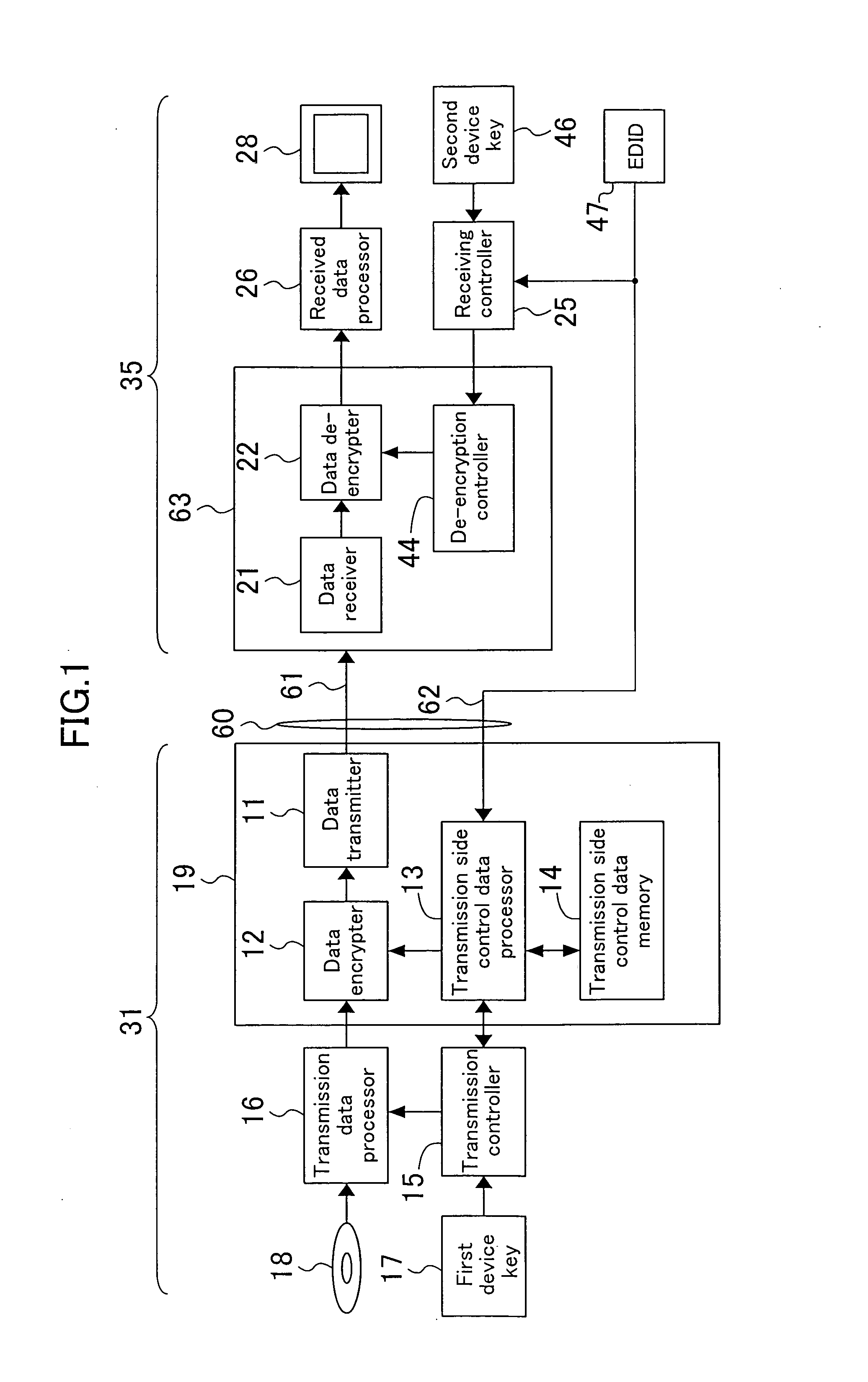
[0063]FIG. 1 is a block diagram illustrating a transmitting device according to a first embodiment of the present invention. In FIG. 1, a display device 35 connected to a transmitting device 19 is shown to make it easy to describe the device. The display device has the same configuration as that of FIG. 4.

[0064] As shown in FIG. 1, the transmitting device 19 of this embodiment is characterized by including transmission side control data memory 14 for storing EDID 47 of the display device 35 and a transmission side control data processor 13.

[0065] The transmitting device 19 of this embodiment is part of a transmission side processing device 31 such as a DVD player. Specifically, the transmission side processing device 31 includes a first memory for holding a first device key, a transmission controller 15 connected to the first memory, a transmission data processor 16, and a transmitting device 19.

[0066] The transmitting device 19 includes the transmission side control data memory ...

second embodiment

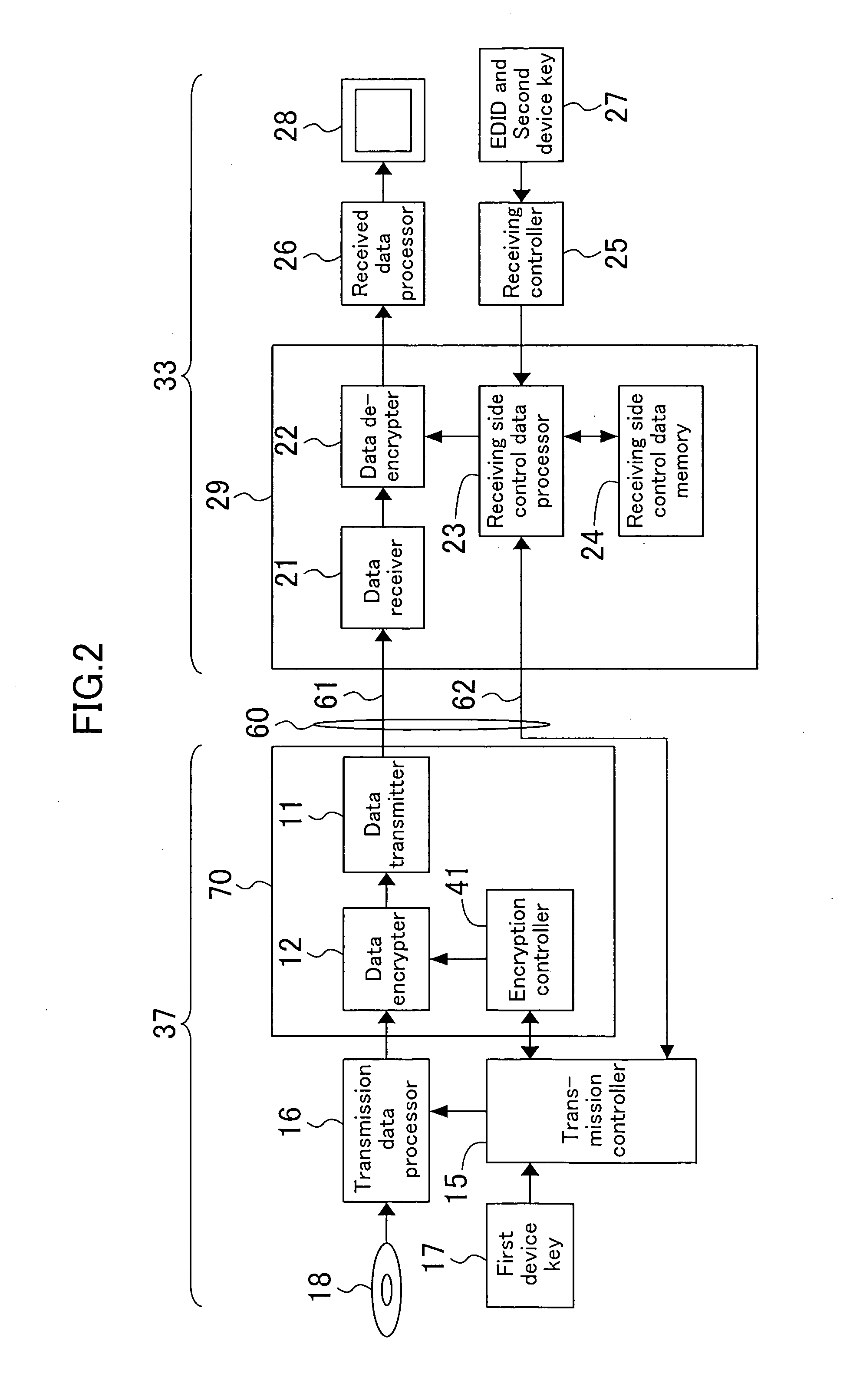
[0085]FIG. 2 is a block diagram illustrating a receiving device according to a second embodiment of the present invention. In FIG. 2, a transmission side processing device 37 having the same configuration as that of the known transmission side processing device is shown to make it easy to describe the device.

[0086] As shown in FIG. 2, a receiving device 29 according to the second embodiment is, for example, part of the display device 33 and is characterized by including a receiving side control data memory 24 for storing the EDID and information necessary for authentication of equipment and a receiving side control data processor 23.

[0087] The display device 33 of FIG. 2 includes a receiving device 29 connected to a transmission line 60 including a high-speed bus 61 and a low-speed bus 62, a fourth memory for holding receiving side information 27 including the EDID and a second device key, a receiving controller 25 for controlling the authentication operation of the receiving devi...

third embodiment

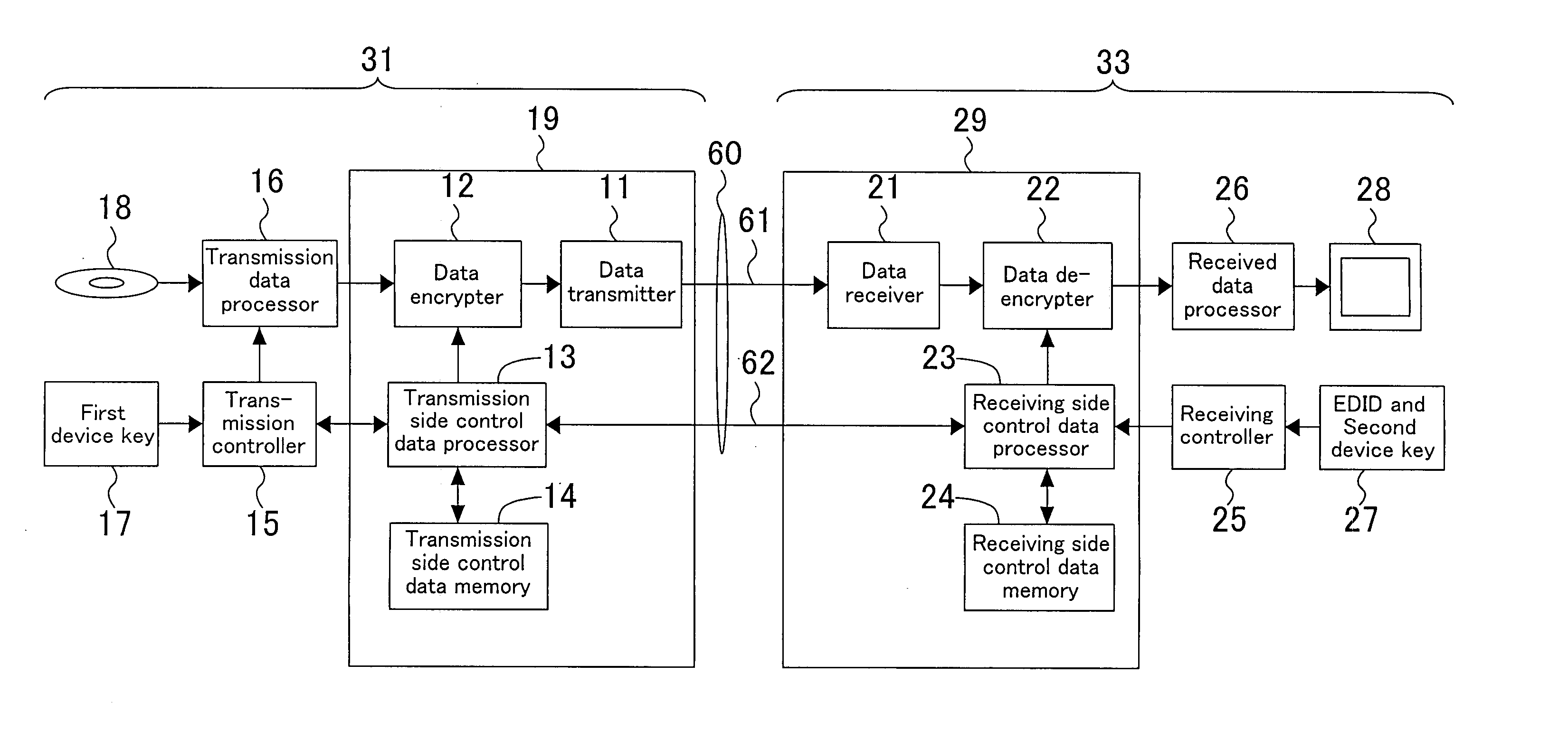
[0108]FIG. 3 is a block diagram illustrating a transmitting / receiving system according to a third embodiment of the present invention. As shown in FIG. 3, the transmitting / receiving system of this embodiment is a combination of the transmitting device 19 of the first embodiment shown in FIG. 1 and the receiving device 29 of the second embodiment shown in FIG. 2. In FIG. 3, each member also shown in FIGS. 1 and 2 is identified by the same reference numeral. Moreover, description of each member of which the operation has been already described will be omitted. Moreover, in this embodiment, the case where the transmission line 60 is based on the DVI standard and the data encrypter 12 and the data de-encrypter 22 performs encryption and de-encryption based on the HDCP standard, respectively, will be described as an example.

[0109] In the display device 33, the receiving controller 25 reads out the receiving side information 27 and makes the receiving side control data memory 24 store th...


PUM


Abstract

A transmitting device includes a transmission side control data memory. A receiving device includes a receiving side control data memory. In an operation state, EDID, a device key for and HDCP and the like are stored in the receiving side control data memory. Subsequently, the EDID and information necessary for HDCP authentication are copied from the receiving side control data memory to the transmission side control data memory through the DDC. A transmission controller accesses the transmission side control data memory and executes plug-and-play and HDCP authentication. The DDC realizes a one-to-one connection between the transmitting device and the receiving device. Thus, waveform distortion can be minimized and the length of a cable can be increased in a simple manner.

Description

CROSS-REFERENCE TO RELATED APPLICATION [0001] This application claims priority under 35 U.S.C. §119(a) on Japanese Patent Application No. 2003-282170, the entire contents of which are hereby incorporated by reference. BACKGROUND OF THE INVENTION [0002] 1. Filed of the Invention [0003] The present invention relates to a transmitting device, a receiving device and a transmitting / receiving system which are used for performing high-speed transmission of a video signal. [0004] 2. Description of the Prior Art [0005] Conventionally, a DVI (Digital Visual Interface) standard has been known as an interface for transmitting a digitalized video signal at high speed between a system unit of a computer and a display (e.g., see Japanese Laid-Open Publication No. 2002-314970). [0006] Moreover, as an unauthorized copy protection system of DVI, HDCP (High-bandwidth Digital Content Protection) has been known (see Japanese Laid-Open Publication No. 2002-314970). A known transmitting / receiving system u...

Claims


Application Information

Patent Timeline
IPC IPC(8): H04N5/91H04L9/00H04L9/08H04N7/167H04N21/4363H04N21/4367
CPCG09G5/006G09G2370/047H04L2209/60H04L9/00G09G2370/12
Inventor YANAGISAWA, RYOGO
Owner PANASONIC CORP
Learn More