Variable manipulative strength catheter

Active Publication Date: 2005-02-03
BOSTON SCI SCIMED INC
View PDF21 Cites 13 Cited by
  • Summary
  • Abstract
  • Description
  • Claims
  • Application Information

AI Technical Summary

Benefits of technology

[0020] In order to provide one or more regions of the catheter shaft, or other catheter component(s), with a coolant, heated fluid, or other temperature affecting mechanism, in some embodiments a catheter may be equipped with one or more lumens through which a fluid is passed. While typically the fluid may have an elevated or reduced temperature relative to the surrounding catheter structure, in some embodiments the presence of the fluid itself within the one or more lumens may act to increase the stiffness of the catheter shaft. By varying the pressure of the fluid within the one or more lumens, and / or the temperature, the stiffness of the catheter may be increased or decreased as desired.
[0022] In some embodiments the consistency of the fluid may affect the stiffness of the catheter as well. For example, if a gas or liquid is present in the one or more lumens, the stiffness of the catheter may be increased by cooling the gas or liquid so that it transitions to a gel or even a solid. Where the fluid is a liquid, cooling the liquid to a gel or a solid state will increase stiffness while warming a gelled liquid to a less viscous state will typically reduce stiffness, etc.
[0024] In some embodiments, electrical current may be transmitted along a conductive wire or other member to a portion of the wire that is at least partially electrically resistant in order to produce heat. The heat produced thereby is then conductively or otherwise transmitted to the adjacent portion of the catheter thereby reducing the stiffness of the material in that region. In some embodiments the portion of the wire (or wires) that is at least partially electrically resistant is one or more coils disposed about at least one region of the catheter shaft. In at least one embodiment a portion of the catheter shaft may be constructed from a graphite polymer hybrid material or other electrically conductive polymer(s), such as for example tecophilic material, which may transfer electric current and heat to one or more areas of the catheter. When electric current is directed to the hybrid material by a conductive wire or other device the hybrid material will create heat thereby reducing the stiffness of the catheter in areas adjacent thereto.

Problems solved by technology

However, the inner is typically soft and flexible which often results in poor transmission of push.

Method used


Image

  • Variable manipulative strength catheter
  • Variable manipulative strength catheter
  • Variable manipulative strength catheter

Examples


Embodiment Construction

[0039] While this invention may be embodied in many different forms, there are described in detail herein specific preferred embodiments of the invention. This description is an exemplification of the principles of the invention and is not intended to limit the invention to the particular embodiments illustrated.

[0040] For the purposes of this disclosure, like reference numerals in the figures shall refer to like features unless otherwise indicated.

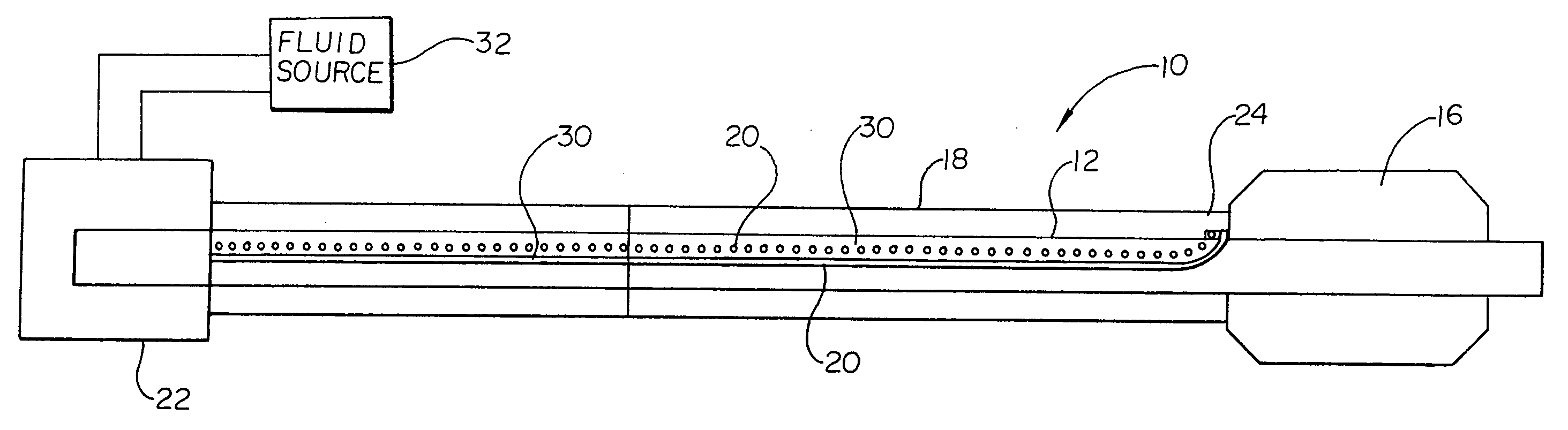
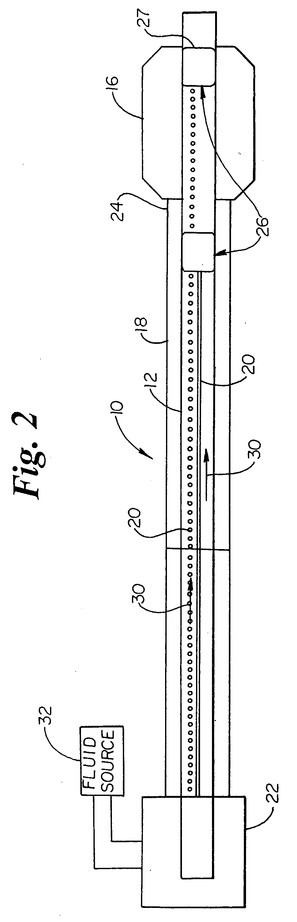
[0041] As indicated above, the present invention may be embodied in a variety of forms. For example, in the embodiment shown in FIG. 1 the invention is directed to a catheter assembly, indicated generally at 10, wherein the catheter 10 is provided with an inner shaft 12 that has a stiffness which may be modified at one or more locations by cooling or heating the desired locations even while the distal end 14 of the catheter 10 is within a patient's body (not shown).

[0042] In the embodiment depicted in FIGS. 1-4 the catheter 10 the inne...


PUM


Abstract

A catheter assembly comprises a catheter which comprises an inner shaft and an outer shaft, and at least one heat transmitting mechanism. At least one portion of at least one of the inner shaft and the outer shaft of the catheter has a predetermined longitudinal stiffness and a predetermined temperature. The predetermined longitudinal stiffness is changed when the predetermined temperature is changed. The at least one heat transmitting mechanism extends distally from the proximal end of the catheter, along the length of the catheter, to a position adjacent to the at least one portion. At least a portion of the at least one heat transmitting mechanism is constructed and arranged to conductively change the predetermined temperature of the at least one portion of the at least one of the inner shaft and the outer shaft.

Description

CROSS-REFERENCE TO RELATED APPLICATIONS [0001] Not Applicable STATEMENT REGARDING FEDERALLY SPONSORED RESEARCH [0002] Not Applicable BACKGROUND OF THE INVENTION [0003] 1. Field of the Invention [0004] Embodiments of this invention are directed to the field of intravascular medical devices, and more particularly to the field of catheters such as angioplasty, neurological and guide catheters, among others, which may be used in various medical procedures such as percutaneous transluminal angioplasty (PTA), percutaneous transluminal coronary angioplasty (PTCA) as well as in procedures involving the placement of medicines and medical devices within the body. [0005] Some embodiments of the invention are directed to all forms of catheters which may be advanced through a body lumen or vessel. Some examples of catheters are over-the-wire (OTW) catheters, such as are described in U.S. Pat. No. 5,047,045; single-operator-exchange (SOE) balloon catheters, such as are described in U.S. Pat. No. ...

Claims


Application Information

Patent Timeline
IPC IPC(8): A61M25/00A61M25/16A61M29/02
CPCA61M25/0054A61M2025/0064A61M25/104
Inventor EIDENSCHINK, TRACEE
Owner BOSTON SCI SCIMED INC
Why Eureka
Try Eureka