
Polarization compensated optical tap

a polarization-compensated, optical tap technology, applied in the direction of optical waveguide light guide, instruments, optics, etc., can solve the problems of small thermal stress generation in materials, low tap pdl, and small stress induced birefringence, so as to achieve greater efficiency and effectively null the effect of polarization dependen

Active Publication Date: 2005-02-03
LUMENTUM OPERATIONS LLC
View PDF13 Cites 14 Cited by
  • Summary
  • Abstract
  • Description
  • Claims
  • Application Information

AI Technical Summary

Benefits of technology

[0015] a portion of the second optical waveguide distinct from the coupling portion having at least one predetermined bend therein which allows light of the first polarization mode to radiate out of the bend portion of the waveguide into a cladding about the bend portion with greater efficiency than light of the second polarization mode thereby effectively nulling a polarization dependence that occurs from the coupling portion, light which remains with the second optical waveguide after passing through the bend portion exiting the output end.
[0017] a portion of the second optical waveguide having at least one bend therein, thereby causing light in the first polarization mode, to radiate out a core of said bend portion with greater efficiency than light in the second polarization mode, so as to substantially null the insertion loss difference IΔ.

Problems solved by technology

However, for silica-on-silicon based optical taps, that is, waveguide devices that comprise doped silica overlying a silicon substrate, low tap PDL is difficult to achieve.
Although fiber drawing is a high temperature process, the low coefficient of thermal expansion (CTE) mismatch means that thermal stresses generated in the materials are small with respect to planar silica-on-silicon devices and so stress induced birefringence is equally small in such optical fiber.
In contrast, silica-on-silicon devices such as planar waveguides have very large CTE mismatches between core, cladding, and substrate materials resulting from the common necessity to deposit final overcladding layers with a much lower softening temperature than the already etched core layers.
Thermal stresses are induced in the device during processing which lead to stress induced birefringence in the waveguiding region.
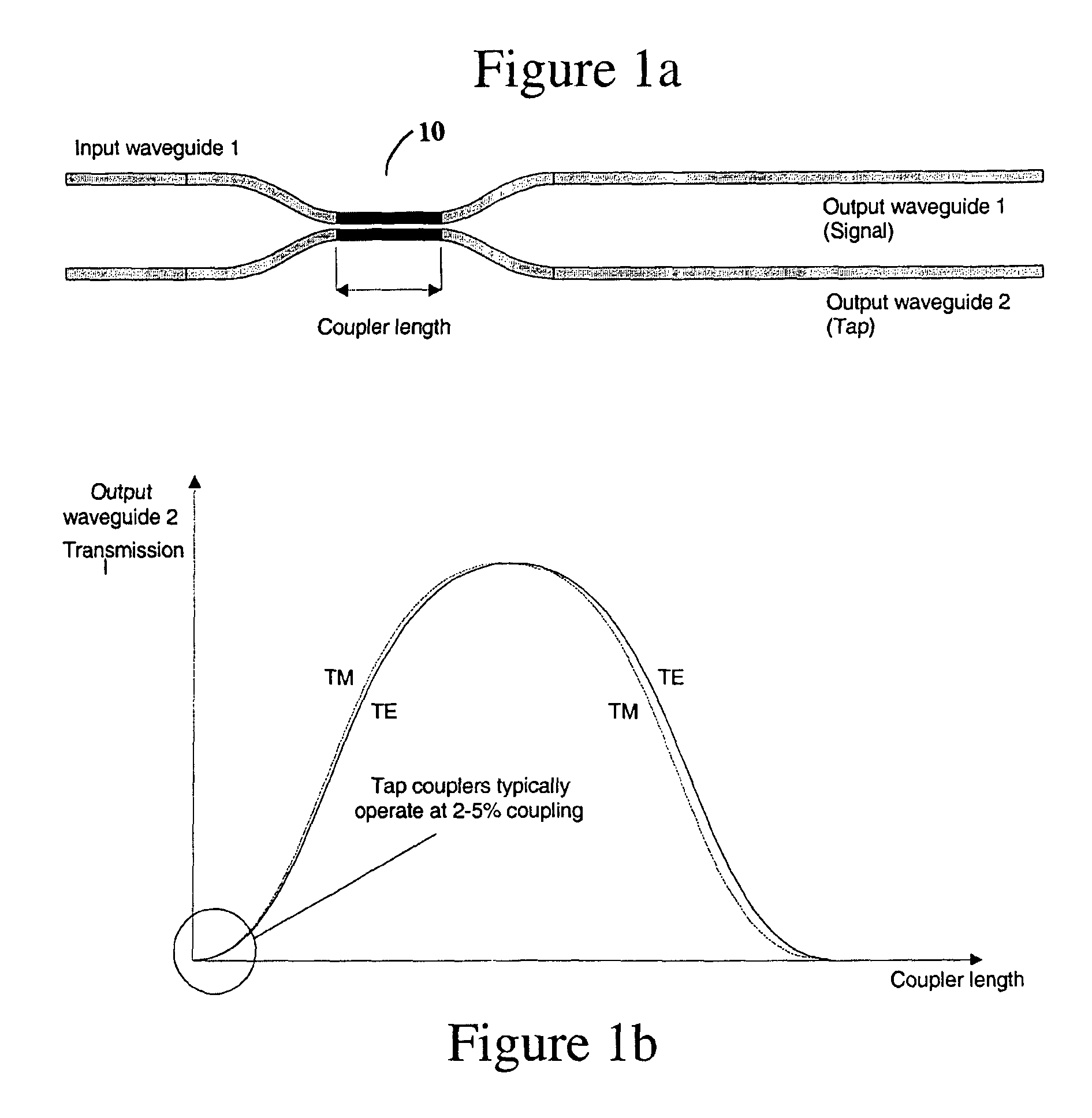
Even though the tap is designed for very small coupling ratios, the real data shows that the PDL resulting from PDCR is still at an unacceptable level even for a tap ratio of −15 dB.

Method used


Image

  • Polarization compensated optical tap
  • Polarization compensated optical tap
  • Polarization compensated optical tap

Examples


Embodiment Construction

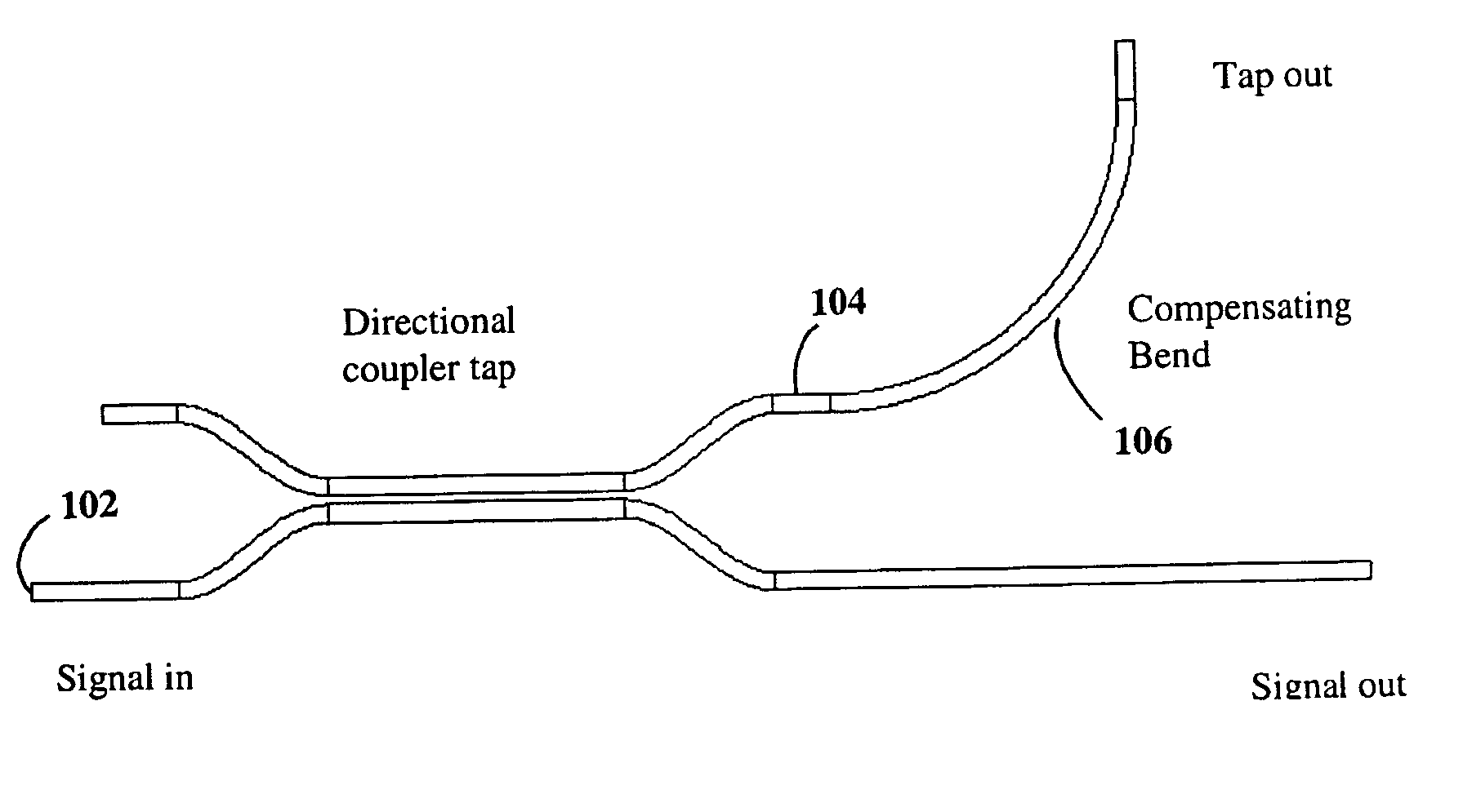
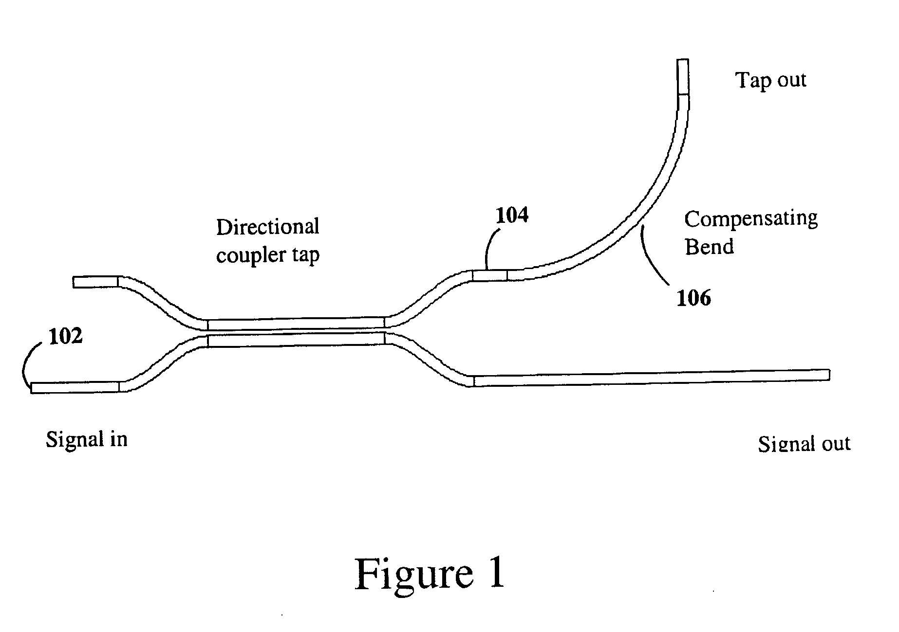
[0036] Referring now to FIG. 1, a waveguide circuit a circuit is shown which conveniently and inexpensively compensates for the polarization dependence of a tap for a silica-on-silicon waveguide device. An input port 102 is optically couple by way of a directional coupler 100 to an output branch arm 104. The low PDL tap function is achieved through the use of a small radii bend 106 on the tapped or branch arm. A same phenomenon that causes the TM polarization to more readily couple between waveguides in a directional coupler also causes a higher polarization dependent bend loss for small radii bends.

[0037] In essence, the TM mode is less well confined so that it both couples between waveguides more easily and radiates from bends more readily than TE modes.

[0038] Because TM modes couple more strongly to the tap or branch waveguide from a trunk waveguide the tapped power level within the branch is slightly higher for the TM polarization than TE. This is illustrated in FIG. 3c at the...


PUM


Abstract

A polarization compensated planar waveguide branch is disclosed having a planar optical trunk waveguide for transporting a linearly un-polarized optical signal having TE and TM modes. A planar optical branch waveguide, capable of supporting TE and TM modes is optically coupled to the trunk waveguide such that at least a portion of an optical signal propagating within the trunk waveguide will couple into the branch waveguide with an undesired imbalance, having stronger TM mode coupling than TE mode coupling for the at least the portion of the optical signal which couples into the branch waveguide from the trunk waveguide. A portion of said branch waveguide downstream from a region where coupling takes place between the trunk and branch waveguides or a waveguide portion optically coupled thereto, receives the at least a portion of the optical signal, and has at least a predetermined bend with a predetermined radius for compensating for the unwanted imbalance in the TM and TE mode caused by light optically coupling into the branch from the trunk waveguide.

Description

FIELD OF THE INVENTION [0001] This invention relates to an optical waveguide tap, which has substantially no polarization dependent loss from an input end to and output tap end. BACKGROUND OF THE INVENTION [0002] Optical taps are used in many optical networks in such applications as power balancing, signal monitoring or feedback control for amplification or attenuation purposes. An optical tap operates by diverting or ‘tapping’ a small, predetermined portion of the signal power that can then be measured to determine the power in the main signal without appreciably attenuating that signal. Although optical taps are typically used to tap a small portion of an input signal, they may tap more than 50% of an input signal. [0003] The requirements optical tap are generally low insertion loss for the signal channel and minimal wavelength dependent loss (WDL) and polarization dependent loss (PDL) for the tapped channel. [0004] Polarization dependent loss is defined to be a measure of peak-to...

Claims


Application Information

Patent Timeline
IPC IPC(8): G02B6/12G02B6/125G02B6/126G02B6/26G02B6/28
CPCG02B6/125G02B2006/12119G02B6/126
Inventor DOUGHERTY, DAVID J.SUN, PANG-CHENHARWOOD, DUNCAN W.
Owner LUMENTUM OPERATIONS LLC
Learn More