
Packet reassembly and deadlock avoidance for use in a packet switch

a packet switch and deadlock technology, applied in the field of communication, can solve the problems of high complexity and cost of building such a large-capacity router, significant affecting the power consumption and cost of the system, and memory technology very often becoming a bottleneck

Inactive Publication Date: 2005-02-03
POLYTECHNIC INST OF NEW YORK
View PDF61 Cites 76 Cited by
  • Summary
  • Abstract
  • Description
  • Claims
  • Application Information

AI Technical Summary

Benefits of technology

[0036] The present invention may be used to prevent a deadlock. The present invention may do so by guaranteeing (e.g., reserving) at least one cell space for all partial packets. If the destination queue for a partial packet has a non-zero outstanding cell counter, the link doesn't need to reserve a cell space in the downstream cell memory. However, if the outstanding cell counter for a partial packet is equal to zero, at least one cell space should be reserved to prevent a deadlock situation. That is, if the outstanding cell counter for the partial packet is greater than 0, the downstream cell memory assigns at least one cell space for the partial packet. This ensures that the EOP cell can be forwarded to its destination.

Problems solved by technology

It still remains a challenge to build a very large IP router with a capacity of tens Tbps or more.
The complexity and cost of building such a large-capacity router is much higher than building an OXC.
Memory technology very often becomes a bottleneck of a packet switch system.
Interconnection technology significantly affects a system's power consumption and cost.
As a result, designing a good switch architecture that is both cost-effective and scalable to have a very large capacity remains a challenge.
The numbers of switch elements and interconnections are often critical to the scalability and cost of a switch fabric.
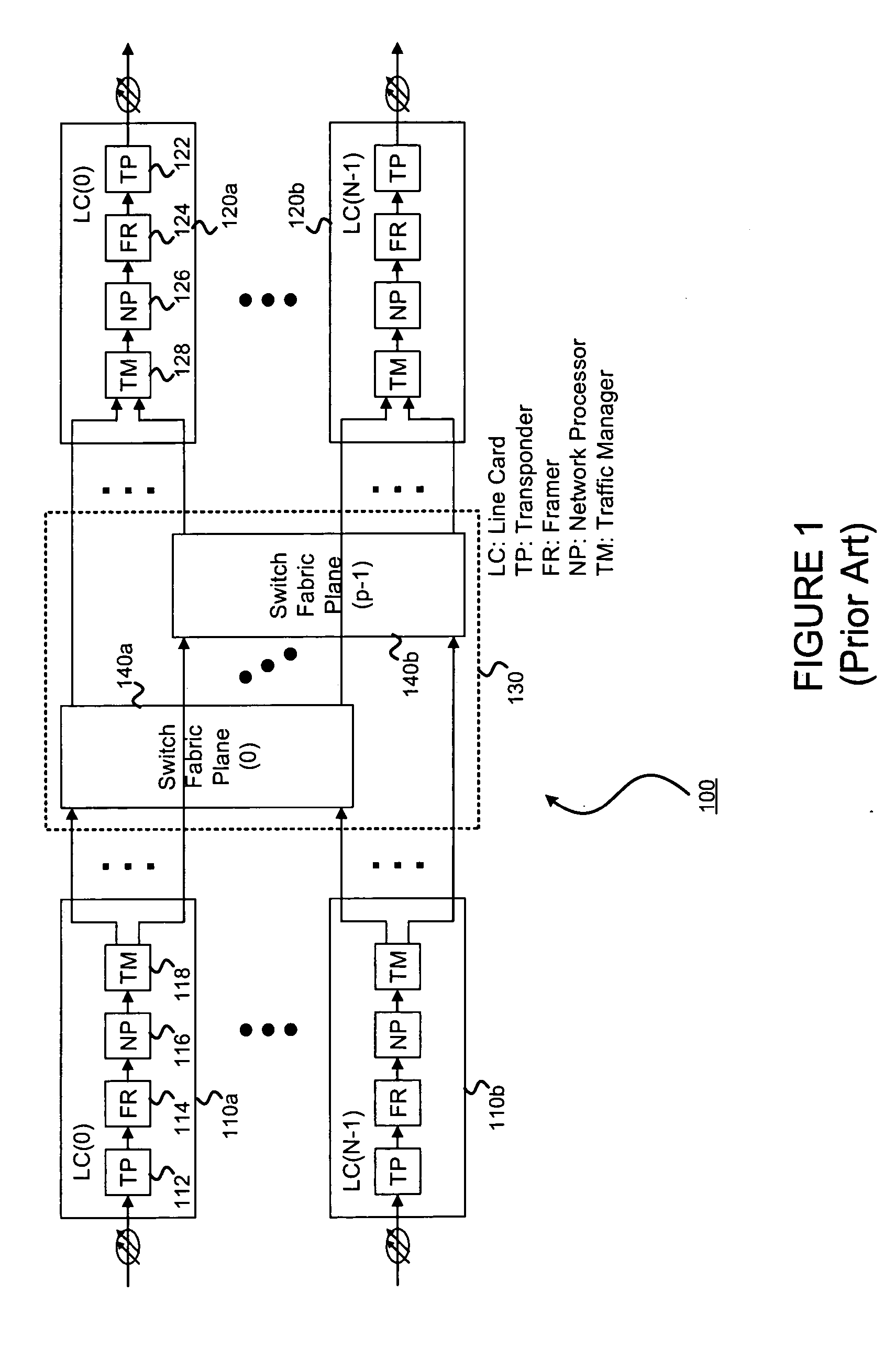
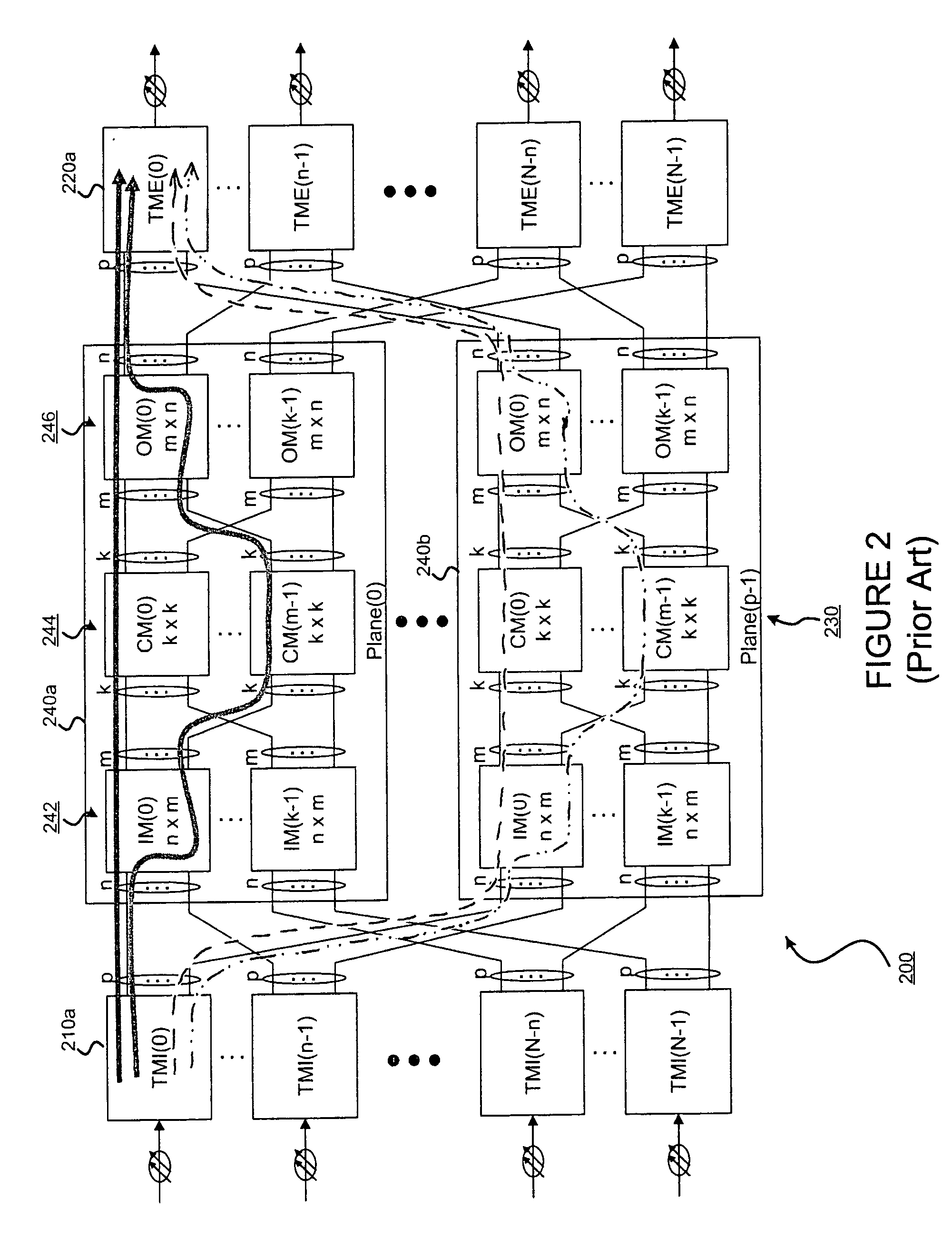
Since the number of switch elements of single-stage switch fabrics is proportional to the square of the number of switch ports, single-stage switch fabric architectures are not attractive for large switches.
Such issues may include packet reassembly and deadlock avoidance.
The CCI scheduling scheme has a major drawback in that the number of reassembly queues (RAQs) can become very large in certain switch fabrics.

Method used


Image

  • Packet reassembly and deadlock avoidance for use in a packet switch
  • Packet reassembly and deadlock avoidance for use in a packet switch
  • Packet reassembly and deadlock avoidance for use in a packet switch

Examples


Embodiment Construction

[0051] The present invention may involve novel methods, apparatus, message formats, and / or data structures for simplifying packet reassembly, while maintaining fairness and throughput and avoiding deadlock. The following description is presented to enable one skilled in the art to make and use the invention, and is provided in the context of particular applications and their requirements. Thus, the following description of embodiments consistent with the present invention provides illustration and description, but is not intended to be exhaustive or to limit the present invention to the precise form disclosed. Various modifications to the disclosed embodiments will be apparent to those skilled in the art, and the general principles set forth below may be applied to other embodiments and applications. For example, although a series of acts may be described with reference to a flow diagram, the order of acts may differ in other implementations when the performance of one act is not de...


PUM


Abstract

Practical packet reassembly in large, multi-plane, multi-stage switches is possible by using a scheduling technique called dynamic packet interleaving. With dynamic packet interleaving scheduling, if more than one packet is contending for the same output link in a switch module, an arbiter in the switch module gives priority to a partial packet (i.e., to a packet that has had at least one cell sent to the queue). The number of reassembly queues required to ensure reassembly is dramatically reduced (e.g., to the number of paths multiplied by the number of scheduling priorities). Deadlock may be avoided by guaranteeing (e.g., reserving) at least one cell space for all partial packets.

Description

§ 0.1 RELATED APPLICATIONS [0001] This application claims benefit to U.S. Provisional Application Ser. No. 60 / 479,733, titled “A HIGHLY SCALABLE MULTI-PLANE MULTI-STAGE BUFFERED PACKET SWITCH,” filed on Jun. 19, 2003, and listing H. Jonathan Chao and Jinsoo Park as inventors (referred to as “the '733 provisional”). That application is incorporated herein by reference. The scope of the present invention is not limited to any requirements of the specific embodiments described in that application.§ 0.2 FEDERAL FUNDING [0002] This invention was made with Government support and the Government may have certain rights in the invention as provided for by grant number ANTI-9906673 by the National Science Foundation.§ 1. BACKGROUND OF THE INVENTION [0003]§ 1.1 Field of the Invention [0004] The present invention concerns communications. In particular, the present invention concerns large scale switches used in communications networks. [0005]§ 1.2 Background Information [0006] To keep pace with...

Claims


Application Information

Patent Timeline
Patent Type & Authority Applications(United States)
IPC IPC(8): H04L12/28
CPCH04L49/552H04L49/1523
Inventor CHAO, HUNG-HSIANG JONATHANPARK, JINSOO
Owner POLYTECHNIC INST OF NEW YORK
Learn More