
Integrated sensor cable for ranging

a sensor cable and integrated technology, applied in the direction of cable/conductor manufacturing, indication/recording movement, burglar alarm mechanical vibration actuation, etc., can solve the problems of compromising and reducing the performance of the security system, and the design of specific transducer cables is costly

Active Publication Date: 2005-02-03
SENSTAR STELLAR CORP
View PDF17 Cites 42 Cited by
  • Summary
  • Abstract
  • Description
  • Claims
  • Application Information

AI Technical Summary

Benefits of technology

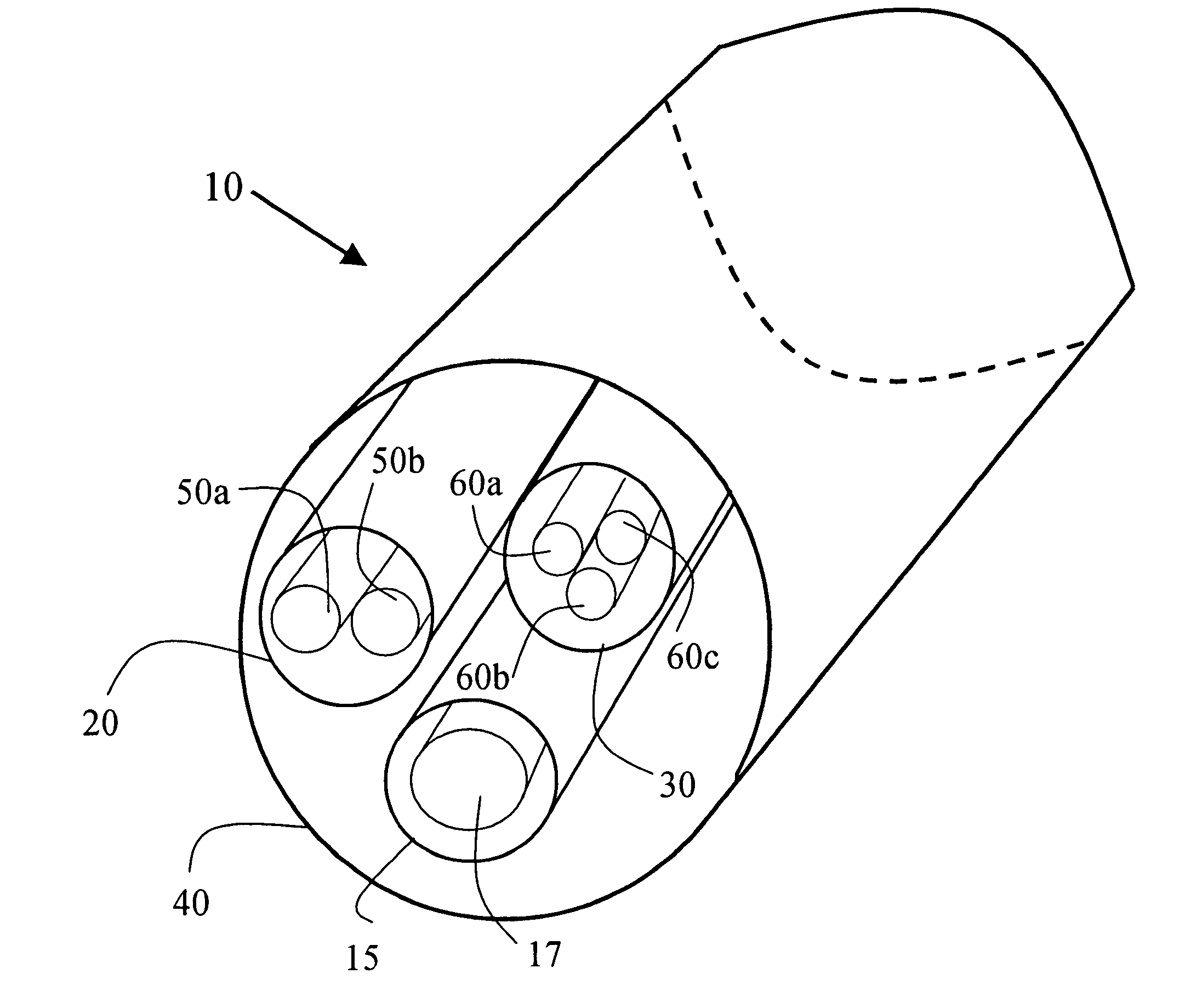
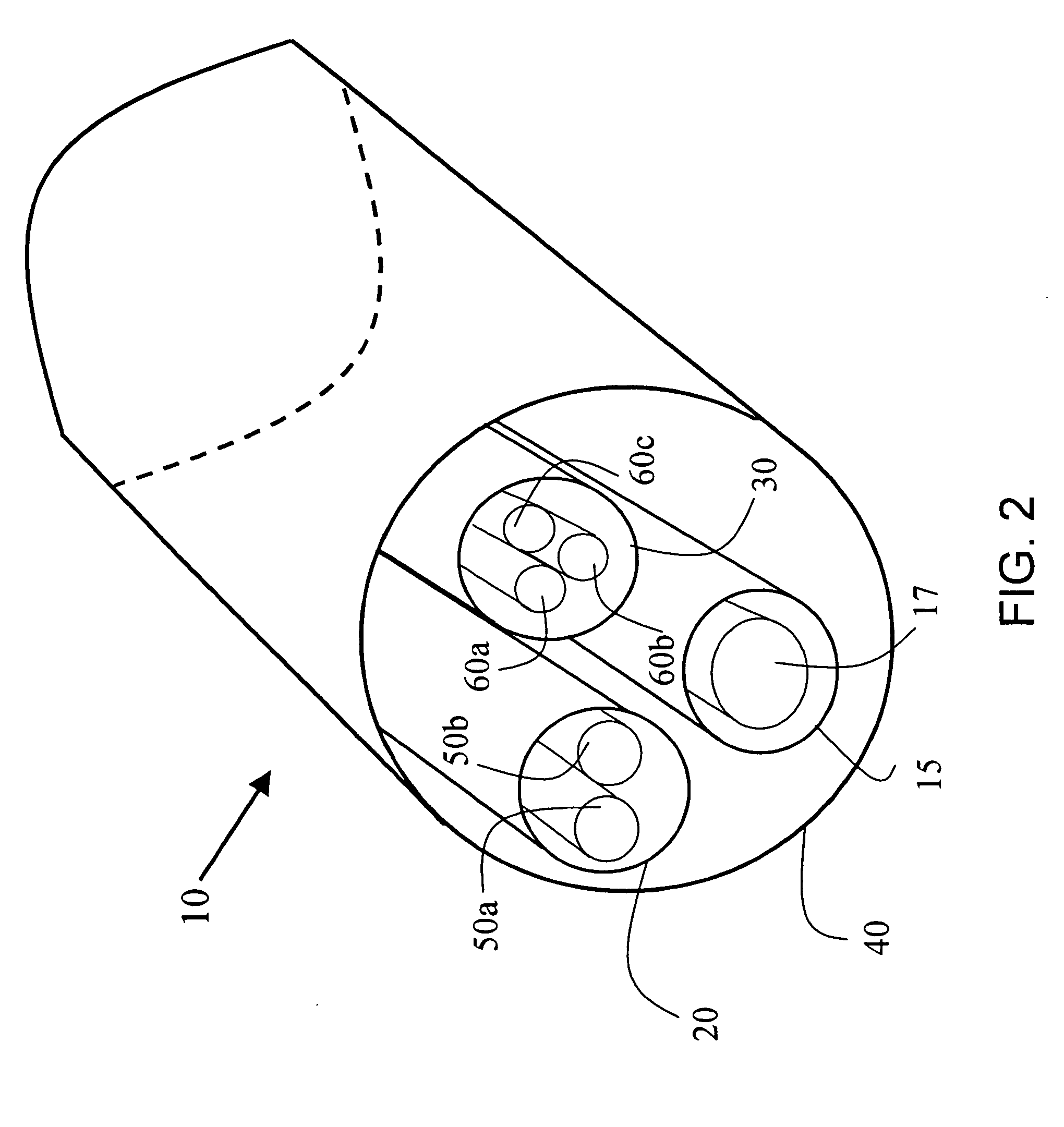
"The present invention provides an intrusion detection system that combines the functions of an active and passive sensor cable system. The system uses a single sensor cable or multiple parallel cables to detect and classify intrusions. The sensor cable system includes a coaxial cable with a loosely disposed conductor that provides range information and a reflectometer that senses changes in impedance caused by an intrusion. The system can be used in fencing and power distribution applications, and can also include other components such as a processor and a reflectometer to provide additional intrusion data. The invention allows for the identification of intrusions based on the reflection of signals injected into the sensor cable system."

Problems solved by technology

These systems face certain challenges not found in indoor security situations.
When functioning under these adverse conditions, the system must continue to maintain a high probability of detection while minimizing false alarms (alarms with unknown causes) and nuisance alarms (environment-related alarms), both of which may compromise and reduce the performance of the security system.
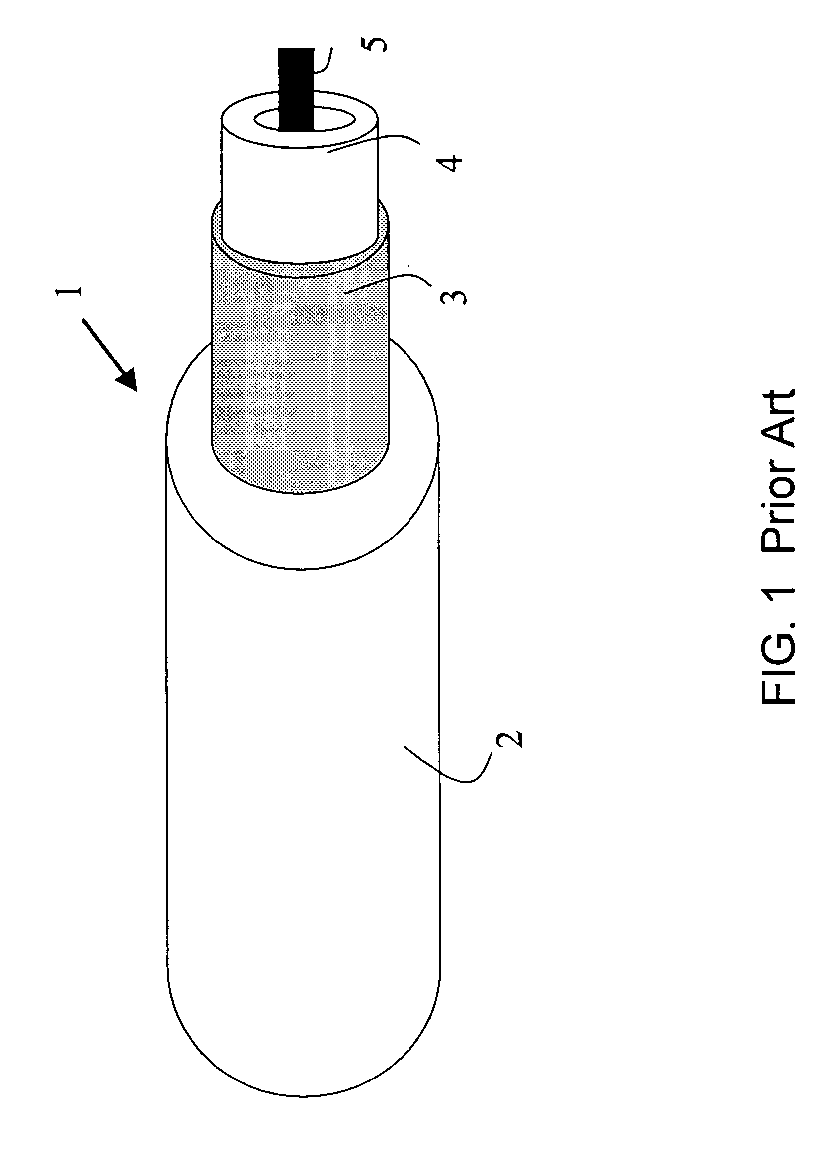
While ranging capabilities of a transducer cable are taught by Harman, the specific transducer cable design is costly, and only allows detection by a single means, namely an impedance change.
However, the dual leaky coaxial cable structure is very expensive to produce, requires the generation and reception of an external electromagnetic field, and provides only a single detection signal caused by the motion of a target in the field.
Additionally, sensing a target within an external field has not been found to be a practical application for mounting on metal structures, such as fences, nor typically above ground such as on walls.

Method used


Image

  • Integrated sensor cable for ranging
  • Integrated sensor cable for ranging
  • Integrated sensor cable for ranging

Examples


Embodiment Construction

[0029] The invention will be described for the purposes of illustration only in connection with certain embodiments. However, it is to be understood that other objects and advantages of the present invention will be made apparent by the following description of the drawings according to the present invention. While a preferred embodiment is disclosed, this is not intended to be limiting. Rather, the general principles set forth herein are considered to be merely illustrative of the scope of the present invention and it is to be further understood that numerous changes may be made without straying from the scope of the present invention.

[0030] For the purposes of this document, the “active ranging” cable system is one where a signal is injected (transmitted) into the cable, and a response signal, either unmodified or modified by an intruder, is sensed by a receiver and analyzed by a processor to determine range or location of the intrusion, similar to radar. For example, the injecte...


PUM


Abstract

An intrusion detection system provides the function of an “active” ranging sensor cable system utilized for identification of the location of the intruder, with that of a “passive” cable detection system, in an integrated cable configuration. This dual function is provided with a single conventional sensing cable optimized for both “active” and “passive” sensing, or in combination with other parallel sensing cables for a “passive” cable component. The “active” cable component includes a coaxial sensor cable having a loosely disposed conductor. A signal is injected into the sensor cable such that a reflection is altered when an intrusion disturbs the cable. Based on the timing of the reflection, a processor, or a reflectometer, identifies the location of the disturbance. The “passive” cable component can be sensitized to detect intrusion via some other sensing phenomenology, such as the triboelectric effect, for triboelectric effect sensing.

Description

BACKGROUND OF THE INVENTION [0001] 1. Field of the Invention [0002] The present invention relates to a perimeter intrusion detection system with integrated sensor cable. More particularly, the present invention relates to a security sensor system, with a specific cable configuration, for locating a disturbance along the length of the sensor cable and for providing intrusion data through a further use of the sensor cable. [0003] 2. Description of the Prior Art [0004] In the field of outdoor intrusion detection systems, there are many security systems for sensing disturbances along a distributed sensor cable deployed about a perimeter. These systems face certain challenges not found in indoor security situations. Environmental conditions, such as temperature extremes, rain, snow, animals, blowing debris, seismic effects, terrain and traffic, must all be taken into account. When functioning under these adverse conditions, the system must continue to maintain a high probability of detec...

Claims


Application Information

Patent Timeline
Patent Type & Authority Applications(United States)
IPC IPC(8): G08B13/12G08B13/16G08B13/186G08B13/24
CPCG08B13/124G08B13/2497G08B13/186G08B13/169G01B7/14G01P13/00G08B13/12G08B13/22G08B13/26H01B11/1895H01B13/016H01B13/0165
Inventor MAKI, MELVIN C.
Owner SENSTAR STELLAR CORP
Learn More