
Heat exchanger device using a two-phase active fluid, and a method of manufacturing such a device

a heat exchanger and active fluid technology, applied in the direction of power cables, lighting and heating apparatus, laminated elements, etc., can solve the problems of large volume occupied by cylindrical rods themselves, large volume is occupied by cylindrical rods, and rigidity, and achieves low cost, facilitate interconnection ducts, and great freedom of design

Inactive Publication Date: 2005-02-03
ATMOSTAT ETUD & RECH
View PDF13 Cites 62 Cited by
  • Summary
  • Abstract
  • Description
  • Claims
  • Application Information

AI Technical Summary

Benefits of technology

An object of the invention is to provide a thermal device using a two-phase active fluid, which device is flat and flexible, presents high degrees of compactness and performance, and includes in its thickness at least one channel of section that is large enough to enable a gas to pass easily without being obstructed by a liquid, and also at least one channel that is small enough to enable a liquid to propagate therein by capillarity. Another object of the invention is also to provide a device that presents little risk of ceasing to operate due to the capillary channels drying out locally.
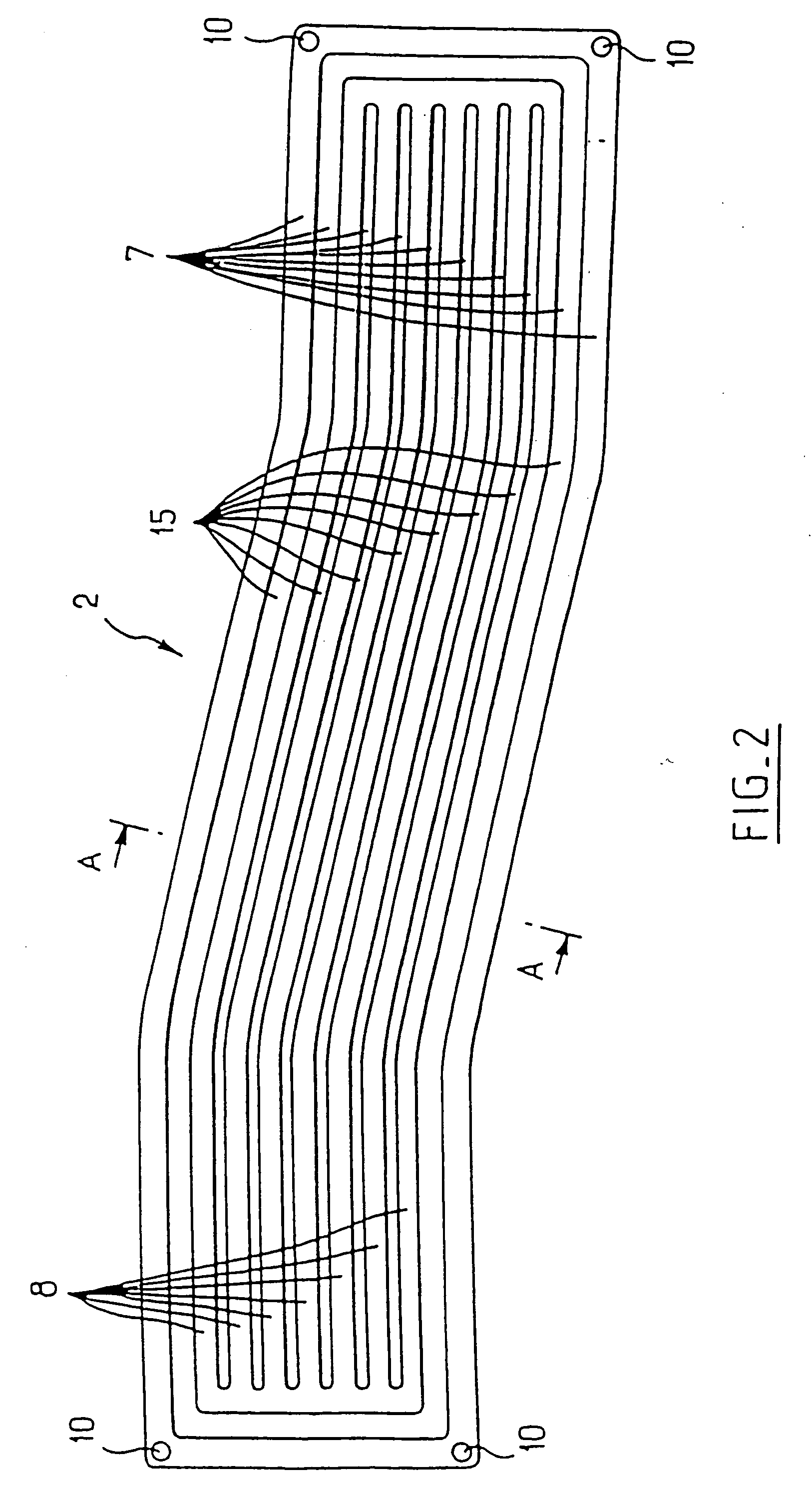
The cutting-out and flat-etching work done on the sheets makes it possible for the device of the invention to have very great freedom in design at low cost, and facilitates interconnecting ducts constituted by a gas transport channel and the capillary channels associated therewith. This feature is particularly remarkable in that the etching and the cutting out are performed simultaneously everywhere over an entire sheet. The corresponding cost is therefore not proportional to the length required for the ducts.

Problems solved by technology

A device of that type is relatively expensive to make and presents drawbacks in certain applications.
For example, its rigidity constitutes one of its drawbacks since that is poorly compatible with allowing pieces to which it is fixed to move when such pieces are subjected to stresses.
However, in devices of that type, a large amount of volume is occupied by the cylindrical rods themselves.
Consequently, the number of capillary channels for any given volume is relatively small, thus limiting the performance of such devices.
This lack of compactness does not provide for good integration with electronic circuits to which the device is fitted.
In that case also, the cylindrical shape of the tubes does not favor optimum compactness or performance.
That device therefore cannot optimize the circulation of each phase of the fluid independently.

Method used


Image

  • Heat exchanger device using a two-phase active fluid, and a method of manufacturing such a device
  • Heat exchanger device using a two-phase active fluid, and a method of manufacturing such a device
  • Heat exchanger device using a two-phase active fluid, and a method of manufacturing such a device

Examples


Embodiment Construction

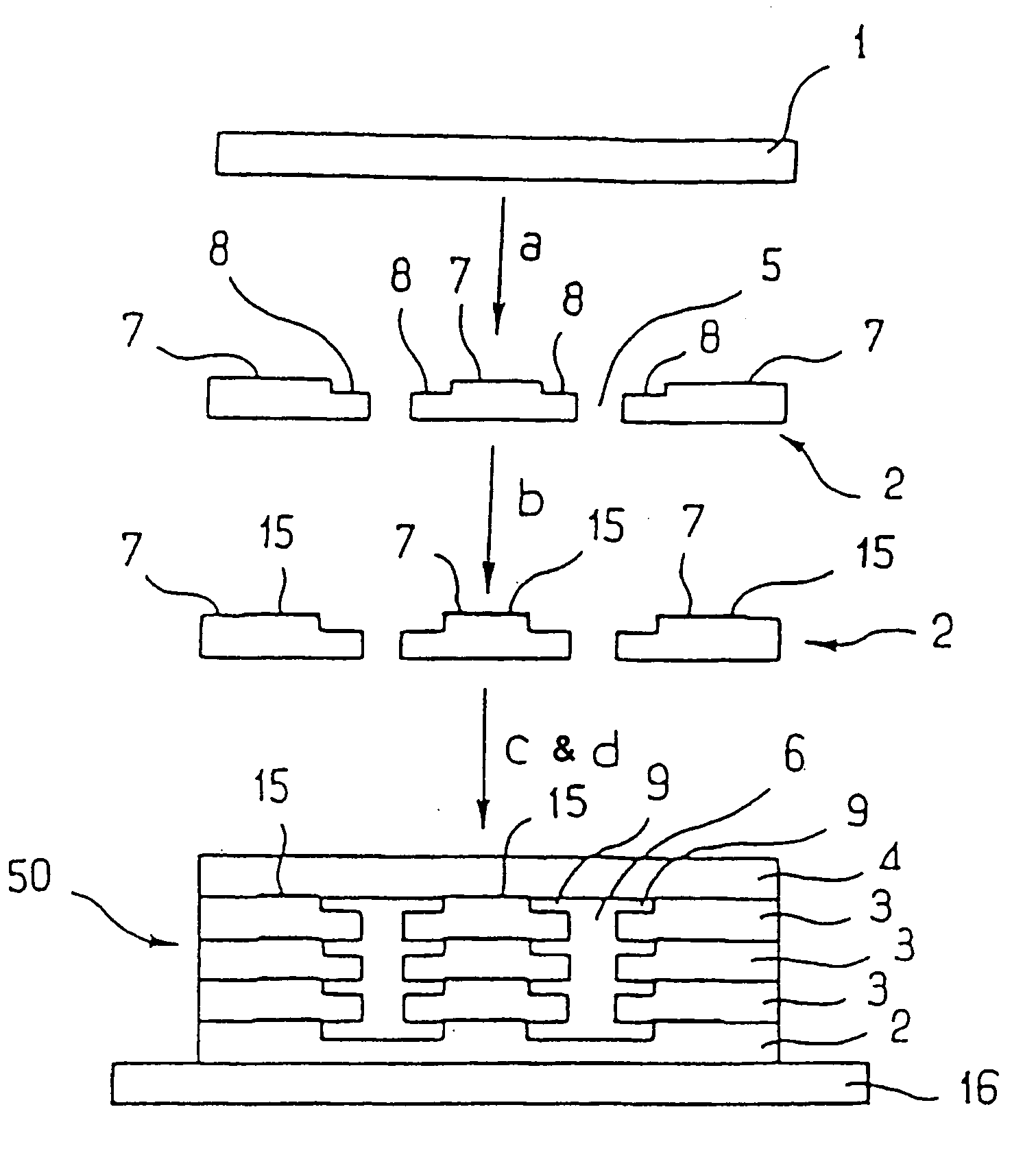
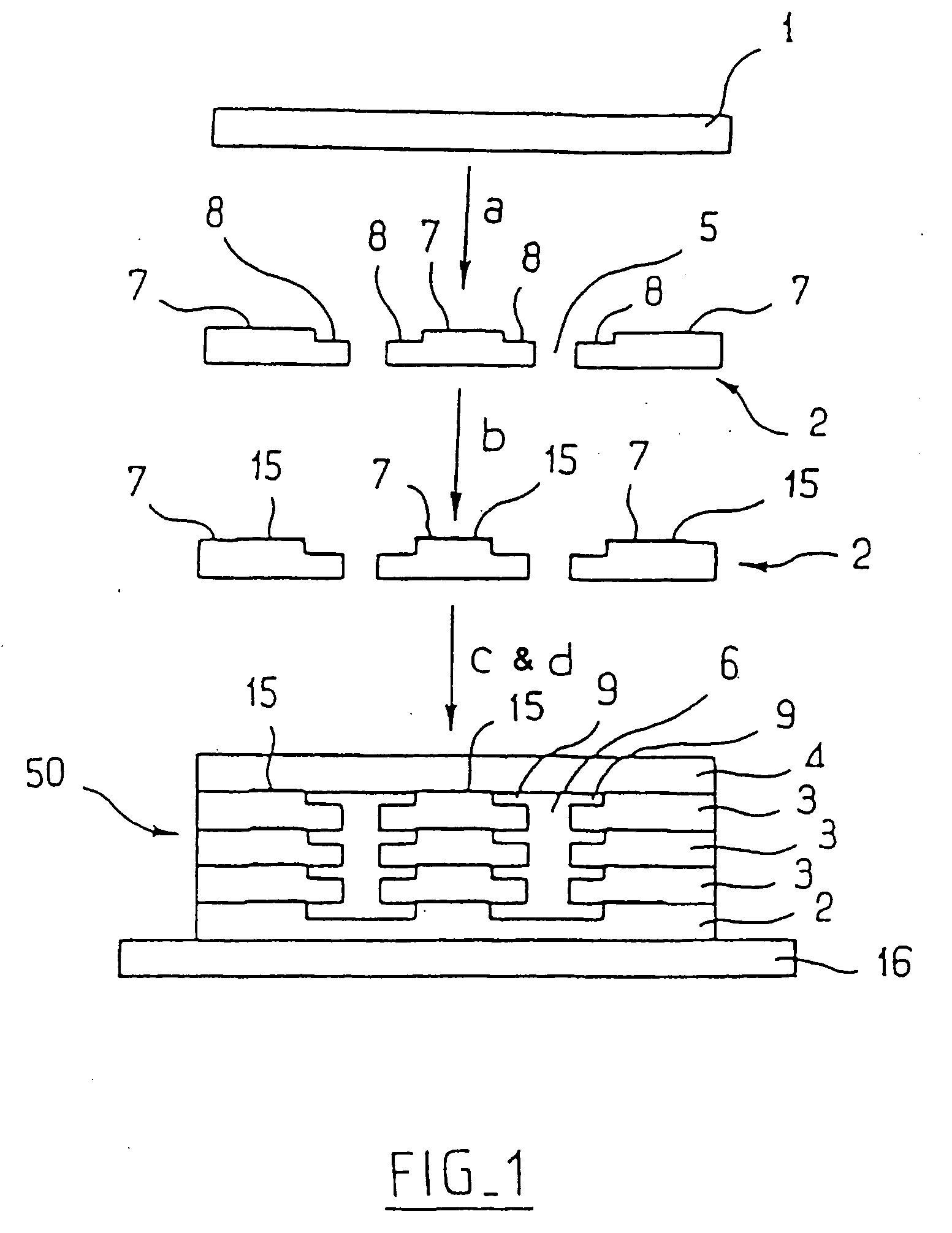
Preferably, but in non-limiting manner, a device of the invention can be made using the method illustrated in FIG. 1.

This method comprises a step a of etching grooves in blank sheets 1, a step b of localized deposition of a bonding material, a step c in which sheets previously prepared in steps a, and b are stacked, and an assembly step d for bonding together the set of sheets stacked in step c so as to form a heat pipe 50, for example.

A blank sheet 1 is constituted by a plate whose thickness preferably lies in the range 1.0 mm to 1 mm. By way of example, the material from which the sheets are made can be a metal. This metal can be copper, nickel, iron, aluminum, or indeed an alloy thereof, such as beryllium aluminum or stainless steel. The nature of the metal constituting the sheets depends on the active fluid used.

Several types of sheet are needed to make a heat pipe 50 of the invention. Starting from a blank sheet 1, it is possible to fabricate bottom sheets 2, intermediat...


PUM


Abstract

A flat sheet structured thermal device using a two-phase active fluid. The device including at least a top sheet, at least two intermediary sheets, and a back sheet stacked longitudinally. Each intermediary sheet has at least one zone etched through its entire thickness to form a gas transport channel. The etched zone being longitudinally bordered by at least one groove formed on the same sheet. The at least one groove contributing to the formation of at least one capillary channel when the sheet is covered by another sheet. The capillary channel is of a section adapted to enable the liquid phase of the fluid to be pumped therein by capillary forces. The device allows fluid to pass reversibly between the capillary channel and the gas transport channel during the liquid / gas or gas / liquid transition due to temperature variations to which at least one zone of the device is subjected.

Description

BACKGROUND OF THE INVENTION 1. Field of the Invention The present invention relates to the field of active fluid heat exchanger devices, and more precisely to those which contain a two-phase fluid and which include capillary channels. 2. Description of the Related Art The term “two-phase” means that the fluid contained in such devices is present in the form of two phases, a liquid and a gas, in order to enable such devices to operate. The term “capillary” is used below to mean channels of section that is very small relative to their length, and above all which are suitable for producing pumping phenomena by capillarity on liquids. Two-phase fluid heat exchanger devices are already known that have capillary channels suitable for producing phenomena of capillarity on the liquid phase, and having gas transport channels in which the gas phase of the fluid is confined, the capillary channels communicating with the gas transport channels. Such devices are used either as closed-loop...

Claims


Application Information

Patent Timeline
Patent Type & Authority Applications(United States)
IPC IPC(8): F28D15/00F28D15/02F28D15/04H01L23/427H05B6/00
CPCF28D15/0233F28D15/046H01L23/427H01L2924/0002Y10T428/24661Y10T428/24744Y10T428/24562H01L2924/00
Inventor DUVAL, JEAN
Owner ATMOSTAT ETUD & RECH
Learn More