Heald frame for weaving machine

a technology of heald frame and weaving machine, which is applied in the direction of positive displacement engine, flexible wall reciprocating engine, textiles and paper, etc., can solve the problems of vibrations that may break the heald frame and/or the heald frame and/or the warp, and one hand noise, so as to reduce the noise and reduce the potential damage

Inactive Publication Date: 2005-02-03
PICANOL NV
View PDF10 Cites 4 Cited by
  • Summary
  • Abstract
  • Description
  • Claims
  • Application Information

AI Technical Summary

Benefits of technology

[0007] The objective of the present invention is the reduction of noise and furthermore the reduction of potential damage caused by heald vibration.
[0009] In this design the healds shall be driven at least in one direction by the damping stop or they shall impact the stop in one direction, as a result of which noise will be significantly reduced. Also, at least when the healds are driven in one direction or when impacted in one direction, damping shall take place and heald vibrations will be substantially reduced. This reduction in noise and adverse effect of vibrations also shall be the case for plays of larger magnitudes, for instance of 2-3 mm or more, and consequently there would be no restriction on the relative movability of the healds in the longitudinal rail direction or in their own longitudinal direction. Means are thus provided to the skilled designer to reduce the danger of noise and creaking movability or shiftability by controlling the play or to trade off somewhat more noise and somewhat greater danger of vibrations against improved heald movability.

Problems solved by technology

These motions result in impacts causing on one hand noise and on the other hand heald vibrations.
At high weaving rates, these motions and particularly the thereby caused vibrations may break the healds and / or the heald frames and / or the warps.
Because the heald play is reduced longitudinally, the longitudinal movability of the healds and their movability in the direction of the rails also is restricted.
As a result, an operator repairing a yarn break may be somewhat hampered and it is even possible that the healds could be bent in the course of making repairs.

Method used


Image

  • Heald frame for weaving machine
  • Heald frame for weaving machine
  • Heald frame for weaving machine

Examples


Embodiment Construction

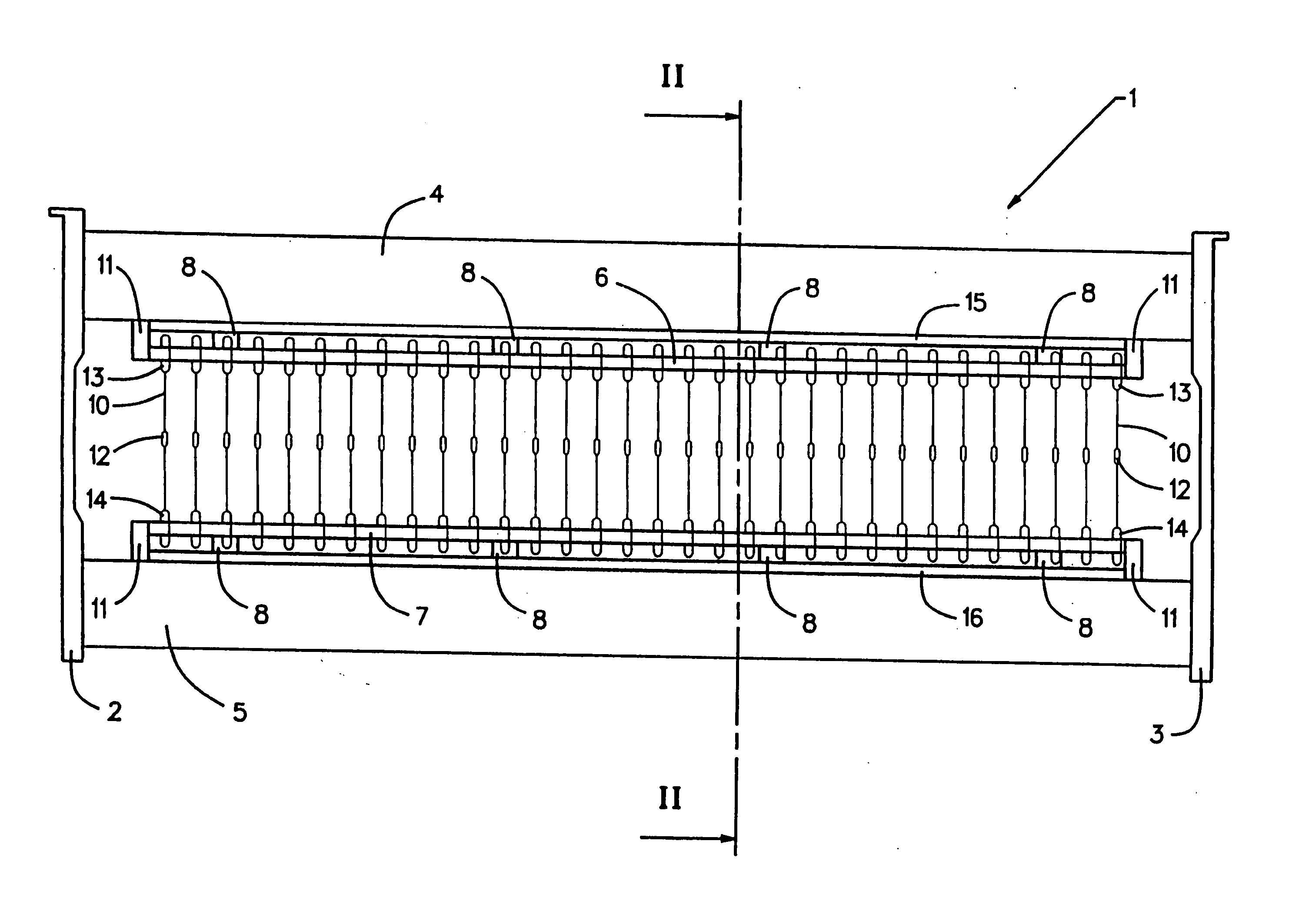
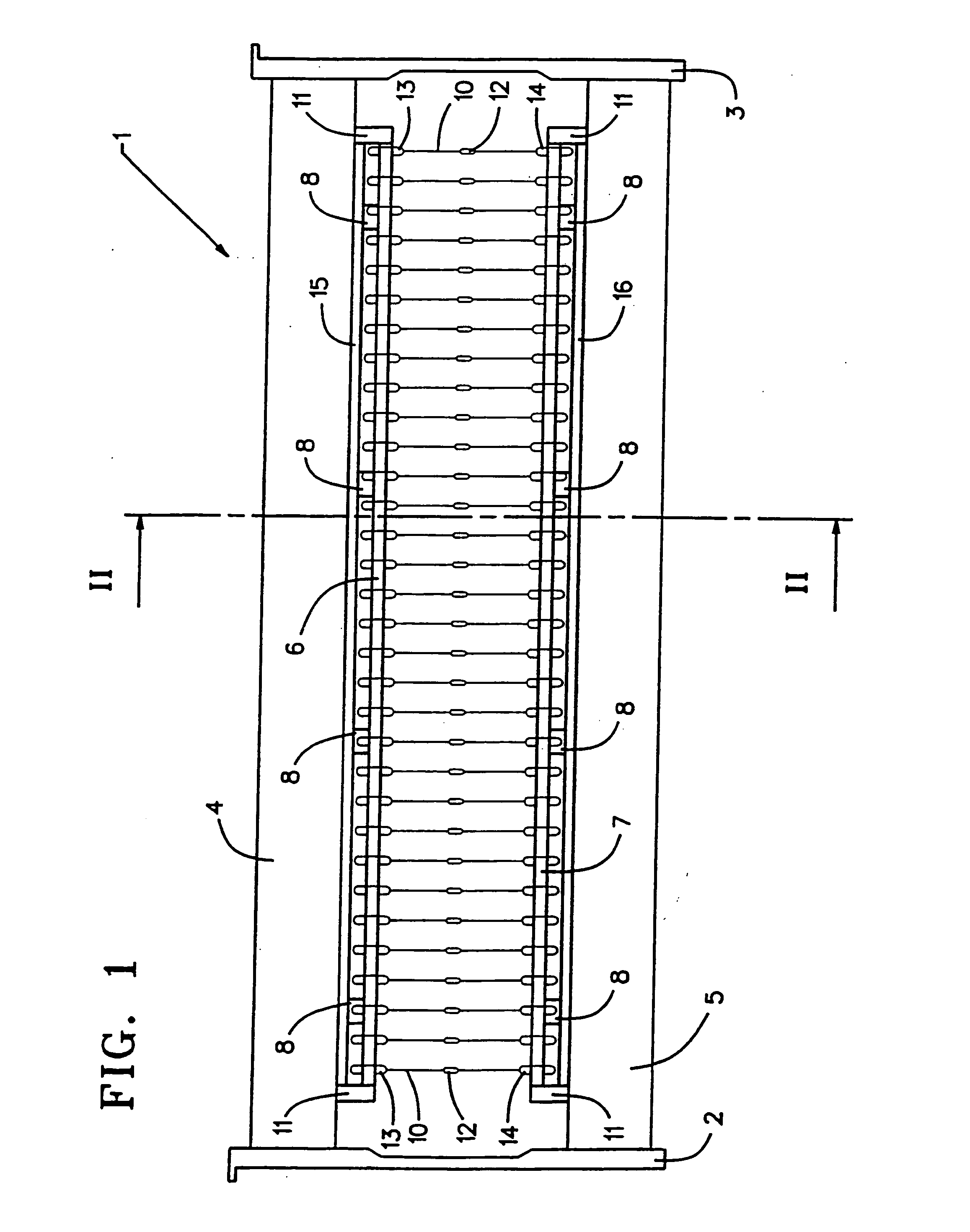
[0015] The heald frame 1 shown in FIG. 1 is a frame consisting of two supporting side sidebars 2 and 3 and two supporting crossbars 4, 5. Rails 6, 7 are affixed by brackets 8 in the zone of the mutually facing sides of the supporting crossbars 4, 5. These rails 6, 7 receive lamellar healds 10 each fitted centrally with a yarn eyelet 12 to receive a warp. The healds 10 are guided by guide elements 13, 14 on the rails 6, 7. The rails 6, 7 are fitted for example at their longitudinal ends with limit stops 11 to prevent the healds 10 from slipping off. The rails include opposed ends located respectively towards and away from the cross bars to which they are attached, said rail ends facing adjacent guide ends defining the limits of play between the rails and the guides, in a well known manner.

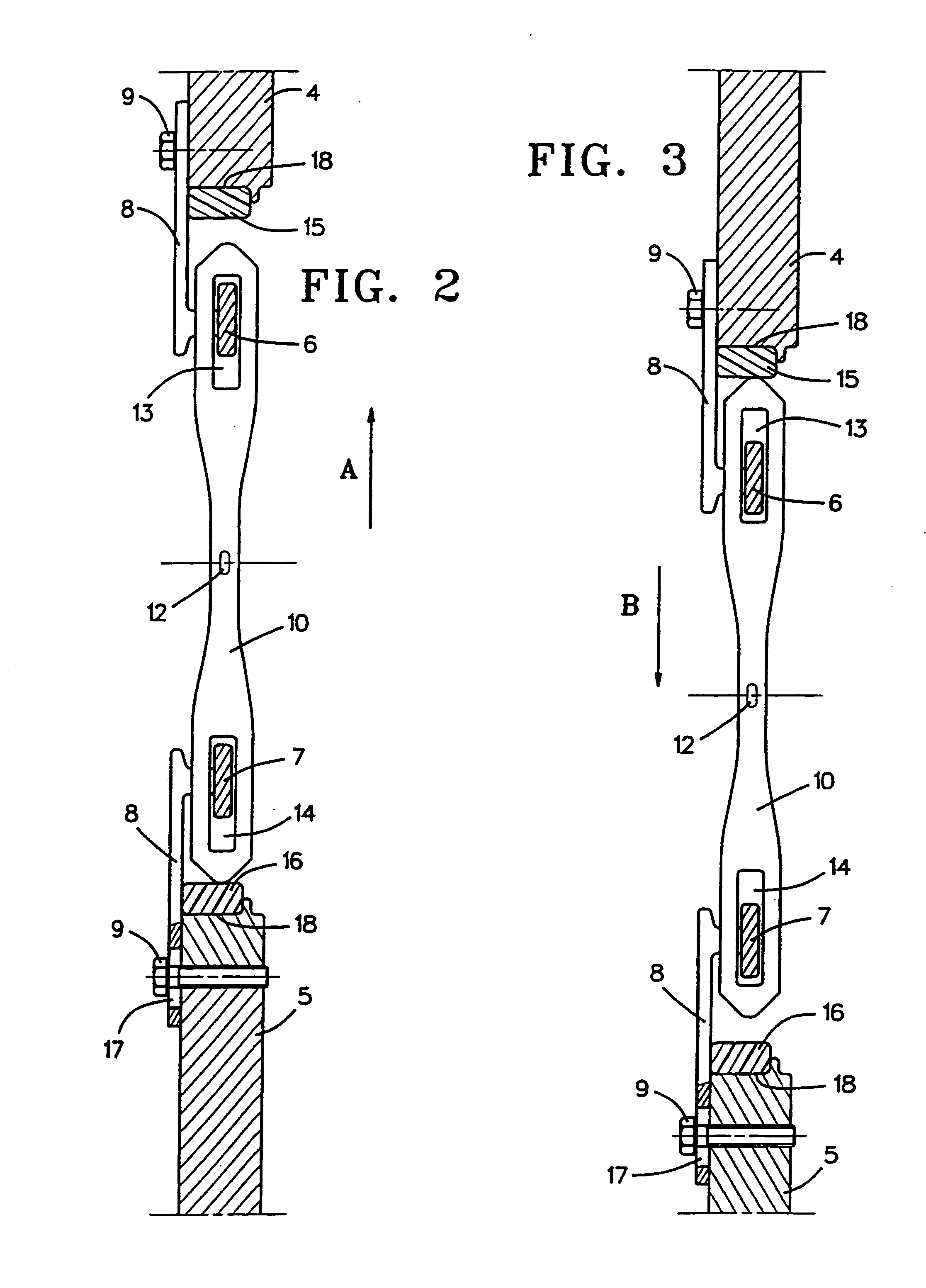
[0016] The ends of the healds 10 are associated with strip shaped heald stops 15, 16 mounted on the crossbars 4, 5 and which drive the healds 10 in the manner described below in relation to FIGS. 2...


PUM


Abstract

A heald frame for a weaving machine includes stops (15, 16) made of a material with shock-absorbing properties associated with the ends of the healds (10). A gap is provided between the heald ends and the stops, such gap ensuring that the healds can be moved along guide rails forming part of the heald frame while reducing noise and potentially damaging vibrations. The healds are held on the guide rails with play and are moved by and limited in their movements in a longitudinal direction by the stops.

Description

CROSS REFERENCE TO RELATED APPLICATION [0001] This application is a continuation application of U.S. patent application Ser. No. 10 / 149,426, filed on Jun. 24, 2002.BACKGROUND [0002] 1. Field of the Invention [0003] The invention relates to weaving machine heald frame fitted with an upper and a lower cross-sectionally contoured rail, hereafter rail, for holding the healds which are held by guide elements located at the ends of the healds to the rails. [0004] 2. Related Art [0005] Several heald frames of this kind constitute a so-called heald frame system. The individual heald frames of this system are alternatingly raised and lowered by a heald frame machine in order to form sheds using heald-guided warps between which fillings may be inserted. The rails and the heald guide elements typically have geometries such that, in one direction of heald frame motion, one of the rails rests by a drive surface against a cooperating surface of the heald guide elements to thereby drive such heald...

Claims


Application Information

Patent Timeline
IPC IPC(8): D03C9/06
CPCD03C9/0691D03C9/0633
Inventor CARDOEN, MARNICKOSTYN, GEERTBEERNAERT, BART
Owner PICANOL NV
Why Eureka
Try Eureka