


Quick Research
Generate reliable direction feasibility study reports for your R&D in just a few steps.

Technical Q&A
Discover and master advanced knowledge NOW. Basics, ideas, possibilities, all at once.

Find Solutions
As an expert in R&D theories, this can generate solutions to your technical problems instantly.

Evaluate Feasibility
Analyze your overall solution with one click, know your potential R&D risks in advance.

Monitor Landscape
Get weekly tech updates, stay abreast of the latest tech innovations and key insights.
Method of balloon pumping and a balloon pump driving apparatus
a technology of balloon pump and driving apparatus, which is applied in the direction of prosthesis, catheter, therapy, etc., can solve the problems of balloon membrane damage, excessive application of balloon pump with load, etc., and achieve the effect of simple structur
- Summary
- Abstract
- Description
- Claims
- Application Information
AI Technical Summary
Benefits of technology
Problems solved by technology
Method used
Image


Examples
first embodiment
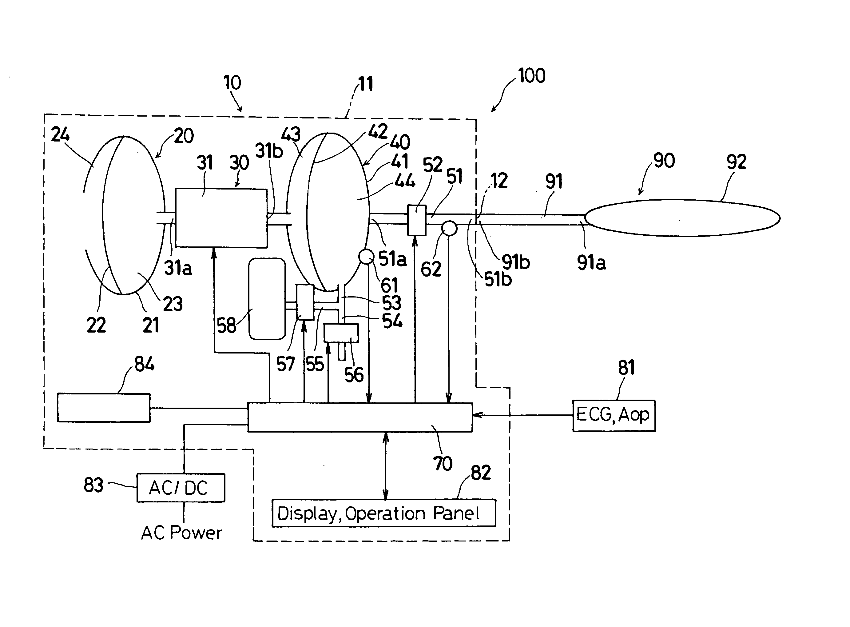
[0036] As illustrated in FIG. 1, a balloon pumping system 100 according to the present invention includes a balloon catheter 90 and a balloon pump driving apparatus 10. The balloon catheter 90 includes a catheter 91 and a balloon 92. The catheter 91 is a long tube with a lumen and is made of a material possessing certain degree of flexibility. The balloon 92 is equipped at a distal end 91a of the catheter 91, i.e. is equipped at an end of the catheter 91 that is away from the balloon pump driving apparatus 10, while the balloon pump driving apparatus 10 is equipped at a proximal end 91b of the catheter 91, i.e. is equipped at an end of the catheter 91 opposite to the distal end 91a.
[0037] The balloon pump driving apparatus 10 is provided with an outer shell of an apparatus housing 11 which houses an oil reservoir 20, an oil pump 30, and an isolator 40. The oil pump 30 includes a pump housing 31 having a first input-output port 31a (a first I / O port) and a second input-output port 3...
second embodiment
[0109] As described above, the output chamber 44 has been charged with the first inflation pressure P1 higher than the pressure required for inflating the balloon 92 until the timing immediately before the pressure control valve 52 is opened. Therefore, once the pressure control valve 52 is opened, the helium gas in the output chamber 44 at a blast flows into the balloon 92. Therefore, according to the present invention, the balloon 92 can be inflated much faster than conventional methods.
[0110] The program then proceeds to step S204 after opening the pressure control valve 52, at which the controller 70 judges whether the pressure control valve 52 has opened for the set period T1set, i.e., judges whether the opening period T1 of the pressure control valve 52 is substantially equal to or greater than the set period T1set (the T1 judging control). When the controller 70 judges that the opening period T1 has not reached the set period T1set, the program returns to step S203. In the me...
third embodiment
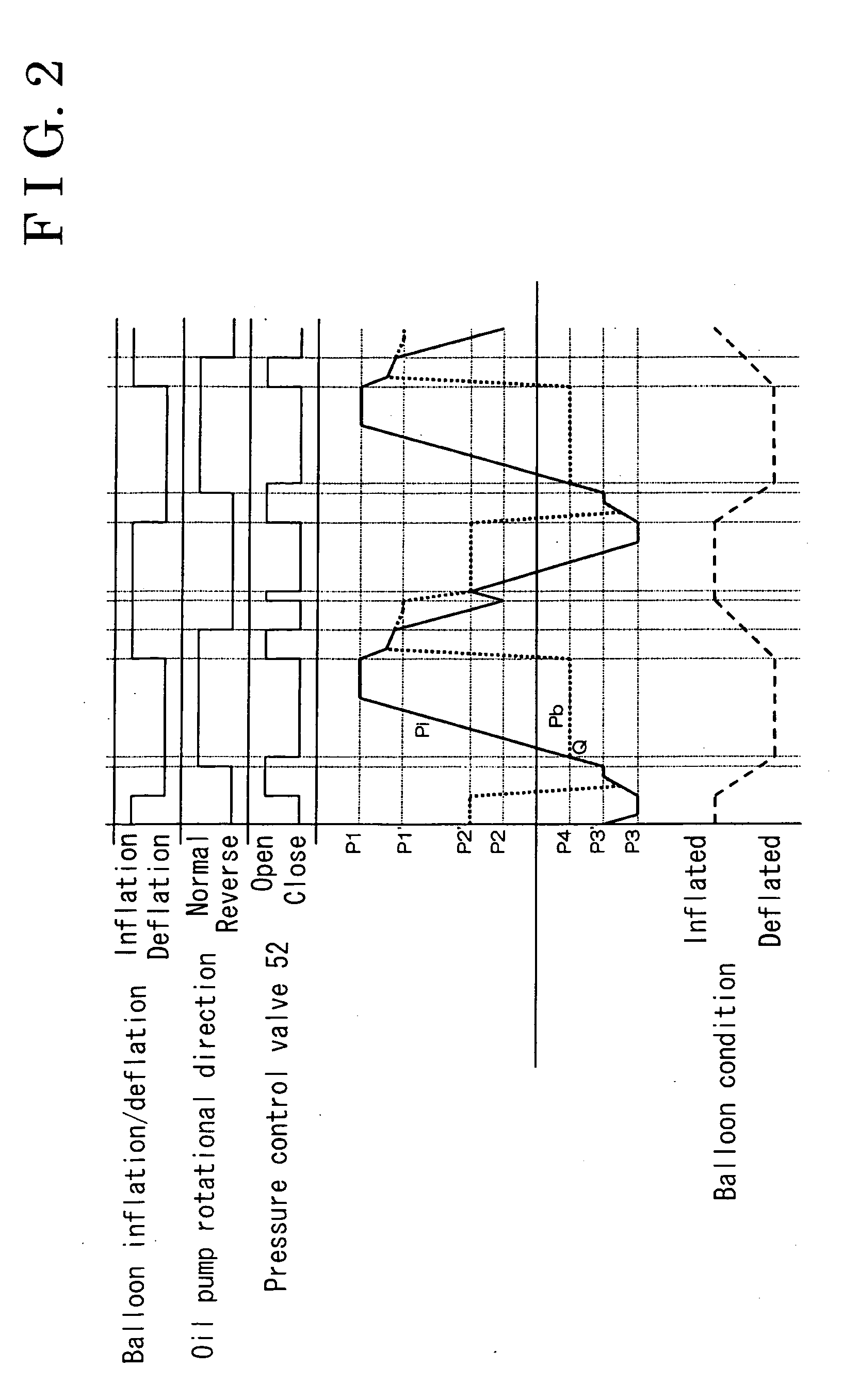
[0145] The controller 70 then judges whether the opening period T1 of the pressure control valve 52 reached the set period T1set (step S304). The controller 70 closes the pressure control valve 52 (step S305). The oil pump 30 is driven for rotation in the reverse direction (step S306), wherein the pressure in the output chamber 44 is decreased. Although the balloon 92 has not completely inflated yet when the pressure control valve 52 is closed, the balloon 92 is inflated as time goes and is completely inflated eventually. When the balloon 92 approaches the completely inflated condition, the amount of helium gas to flow to the balloon 92 is gradually decreased, and the pressure Pb in the balloon 92 becomes a constant pressure value. The controller 70 judges whether the balloon 92 has completely inflated based upon the pressure change rate ÄPb with time (step S307). As explained in FIG. 7, the pressure Pb becomes approximately constant at the pressure P1′. The pressure P1′ is higher t...
PUM
 Abstract
Description
Claims
Application Information
 - R&D Engineer
- R&D Manager
- IP Professional
- Industry Leading Data Capabilities
- Powerful AI technology
- Patent DNA Extraction
Browse by: Latest US Patents, China's latest patents, Technical Efficacy Thesaurus, Application Domain, Technology Topic, Popular Technical Reports.
© 2024 PatSnap. All rights reserved.Legal|Privacy policy|Modern Slavery Act Transparency Statement|Sitemap|About US| Contact US: help@patsnap.com