Plasmatron-catalyst system

a plasma catalyst and plasma technology, applied in the field of plasma catalyst systems, can solve the problem of not extending plasma catalysis, and achieve the effect of reducing the co content of the reforma

Inactive Publication Date: 2005-01-27
MASSACHUSETTS INST OF TECH
View PDF22 Cites 9 Cited by
  • Summary
  • Abstract
  • Description
  • Claims
  • Application Information

AI Technical Summary

Benefits of technology

[0020] In yet another embodiment, the CO content of the reformate is decreased by

Problems solved by technology

Since the intention of the prior art is not to reform all of the fuel, the issues of efficiency, although still relevant, have not heretofore driven the design of a plasmatron system.
Th

Method used


Image

  • Plasmatron-catalyst system
  • Plasmatron-catalyst system
  • Plasmatron-catalyst system

Examples


Embodiment Construction

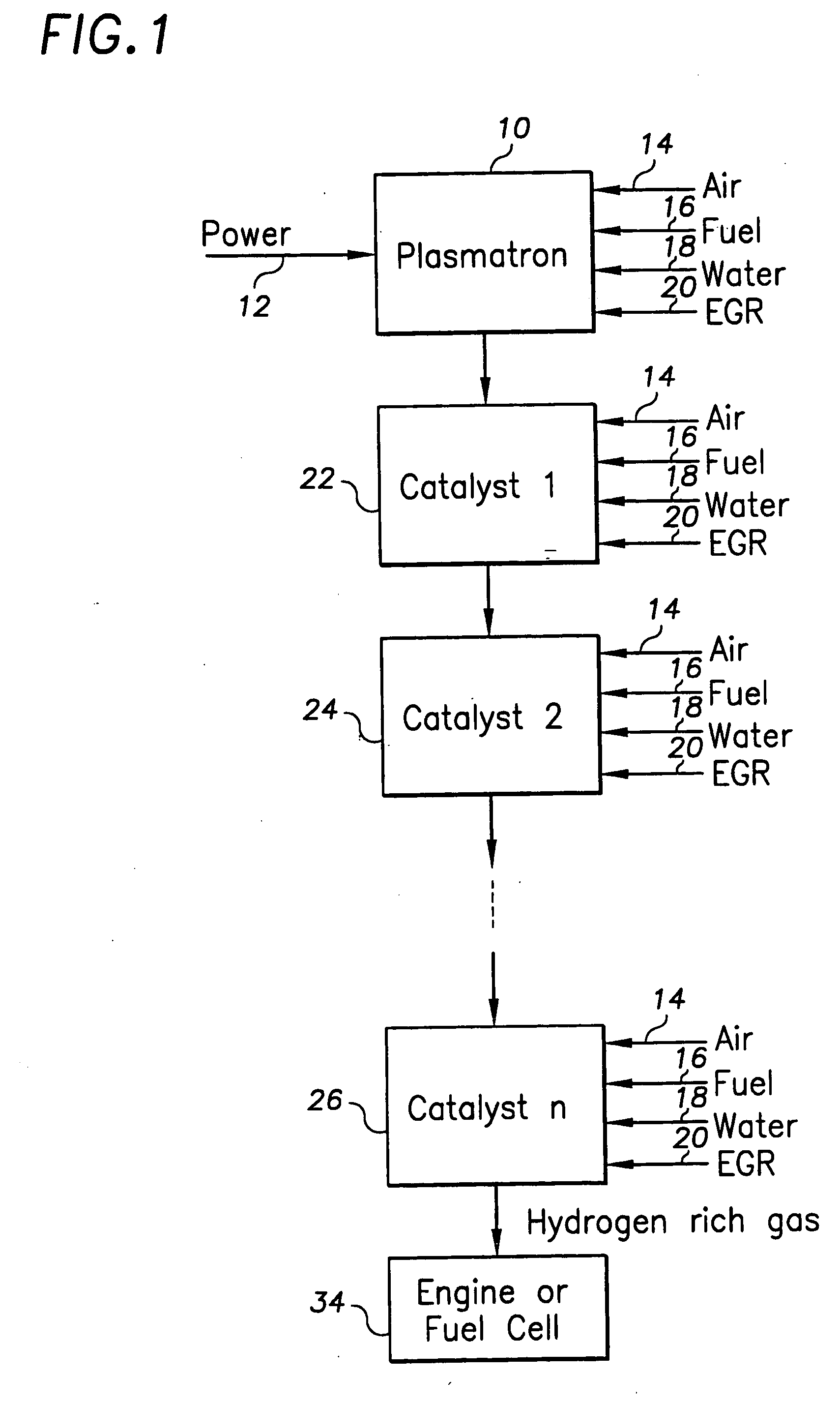
[0026] Water / steam can be used to achieve several objectives in the reforming process. These objectives include use in a water-shift reaction, downstream from the plasmatron and reactor, in order to reduce the CO concentration and increase the hydrogen concentration. Water / steam can also be used to perform steam reforming in which the water / steam reacts with the hydrocarbon fuel to produce hydrogen and CO. Water / steam can also be used in an autothermal reaction in which both air and water / steam are used in order to insure that the exothermicity of the partial oxidation process is balanced by the endothernicity of the steam reforming reaction. In this case, the reforming reaction is energy neutral. The use of water / steam, oxygen and fuel in a plasmatron reactor forms a continuum of possibilities. In the case of partial oxidation, the maximum hydrogen yield is 100%, while when water / steam is added the hydrogen yield can be larger than 100% by virtue of the release of hydrogen from the...


PUM


Abstract

A plasmatron-catalyst system. The system generates hydrogen-rich gas and comprises a plasmatron and at least one catalyst for receiving an output from the plasmatron to produce hydrogen-rich gas. In a preferred embodiment, the plasmatron receives as an input air, fuel and water/steam for use in the reforming process. The system increases the hydrogen yield and decreases the amount of carbon monoxide.

Description

RELATED APPLICATIONS [0001] This application is a continuation-in-part of U.S. application Ser. No. 09 / 182,537 filed Oct. 29, 1998 for “Plasmatron-Catalyst System”, the teachings of which are hereby incorporated by reference. [0002] This invention was made with government support under Contract Number DE-FG07-98ID13601 awarded by the U.S. Department of Energy. The government has certain rights in the invention.FIELD OF THE INVENTION [0003] This invention relates to a plasmatron-catalyst system which can maximize hydrogen yield and decrease the amount of carbon monoxide. BACKGROUND OF THE INVENTION [0004] The pending U.S. application mentioned above, of which this application is a continuation-in-part, discloses and claims the use of a rapid response plasmatron for converting hydrocarbon fuels into hydrogen-rich gases. This process may be carried on-board vehicles. [0005] Converting hydrocarbon fuels into hydrogen-rich gas (reforming) can be achieved with a plasmatron reactor. There ...

Claims


Application Information

Patent Timeline
IPC IPC(8): B01D53/94B01J12/00B01J19/08C01B3/34C01B3/38C01B3/48C01B3/58F01N3/08F01N3/20F02B3/06F02B25/12F02B43/10F02B51/00F02B51/04H01M8/06
CPCB01D53/94Y10S48/08B01J19/088B01J2219/0883B01J2219/0892B01J2219/0894C01B3/342C01B3/38C01B3/48C01B3/583C01B2203/0233C01B2203/0261C01B2203/0283C01B2203/044C01B2203/047C01B2203/066C01B2203/0844C01B2203/0861C01B2203/0866C01B2203/142C01B2203/143C01B2203/1604C01B2203/80C10J2300/1238F01N3/0892F01N3/206F01N2240/28F01N2240/30F01N2610/04F02B3/06F02B25/12F02B43/10F02B51/00F02B51/04F02B2043/106H01M8/0612H01M8/0631H01M8/0662Y02E60/50Y02T10/126Y02T10/32B01J12/002Y02T10/12Y02T10/30Y02P20/129Y02P20/52
Inventor BROMBERG, LESLIECOHN, DANIEL R.RABINOVICH, ALEXANDERALEXEEV, NIKOLAI
Owner MASSACHUSETTS INST OF TECH
Why Eureka
Try Eureka