
Spin-valve magnetoresistive element having fixed magnetic layer of epitaxal laminate including magnetic layer and nonmagnetic layer

a magnetoresistive element and epitaxal laminate technology, applied in the field of magnetic sensors, can solve the problems of preventing such an improvement, difficult to reduce the distance between the top and bottom shield layers, and the magnetization direction of the pinned ferromagnetic layer b>70/b> cannot be appropriately fixed

Inactive Publication Date: 2005-01-27
TDK CORPARATION
View PDF9 Cites 20 Cited by
  • Summary
  • Abstract
  • Description
  • Claims
  • Application Information

AI Technical Summary

Benefits of technology

[0024] A magnetic sensor having a self-fixed magnetic layer and a mechanism of controlling the magnetostriction of the fixed magnetic layer are disclosed to appropriately control the magnetostriction. By exploiting the mechanism described above, a magnetic sensor which can tightly fix the magnetization of a fixed magnetic layer can be provided by appropriately selecting a material for a non-magnetic film which is in contact with the fixed magnetic layer.

Problems solved by technology

However, the shunt loss described above causes deterioration in the magnetic sensor output, thereby inhibiting such an improvement.
However, the large thickness of the structure due to the presence of the thick antiferromagnetic layer makes it difficult to decrease the distance between the top and the bottom shield layers.
However, it was found that, in the structure as that disclosed in Japanese Unexamined Patent Application Publication No. 8-7235 in which the Co films are provided on the buffer layer made of tantalum, the magnetization direction of the pinned ferromagnetic layer 70 cannot be appropriately fixed.
When the coercive force is small, since the magnetization of the fixed magnetic layer fixed in a height direction is liable to be reversed by a mechanical stress (generated when a magnetic sensor impinges upon a surface of a recording medium or generated in manufacturing), reproduction properties become unstable, resulting in degradation in reliability.

Method used


Image

  • Spin-valve magnetoresistive element having fixed magnetic layer of epitaxal laminate including magnetic layer and nonmagnetic layer
  • Spin-valve magnetoresistive element having fixed magnetic layer of epitaxal laminate including magnetic layer and nonmagnetic layer
  • Spin-valve magnetoresistive element having fixed magnetic layer of epitaxal laminate including magnetic layer and nonmagnetic layer

Examples


examples

[0207] The change in magnetostriction of CoFe was measured when the composition ratio of a PtMn layer of the laminate was changed, the laminate made of the PtMn layer and a CoFe layer provided thereon.

[0208] A multilayer film having the following structure was formed and was then annealed at 290° C. for four hours.

[0209] The multilayer film had the structure composed of alumina (1,000 Å), (Ni0.8Fe0.2)60Cr40 (52 Å), PtxMn100-x (30 Å), Co90Fe10 (20 Å), and Ru (9 Å) provided in that order on a silicon substrate.

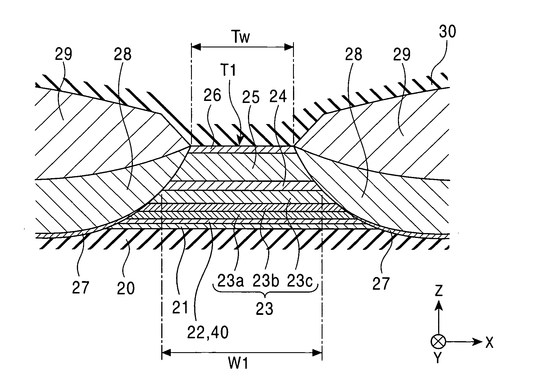
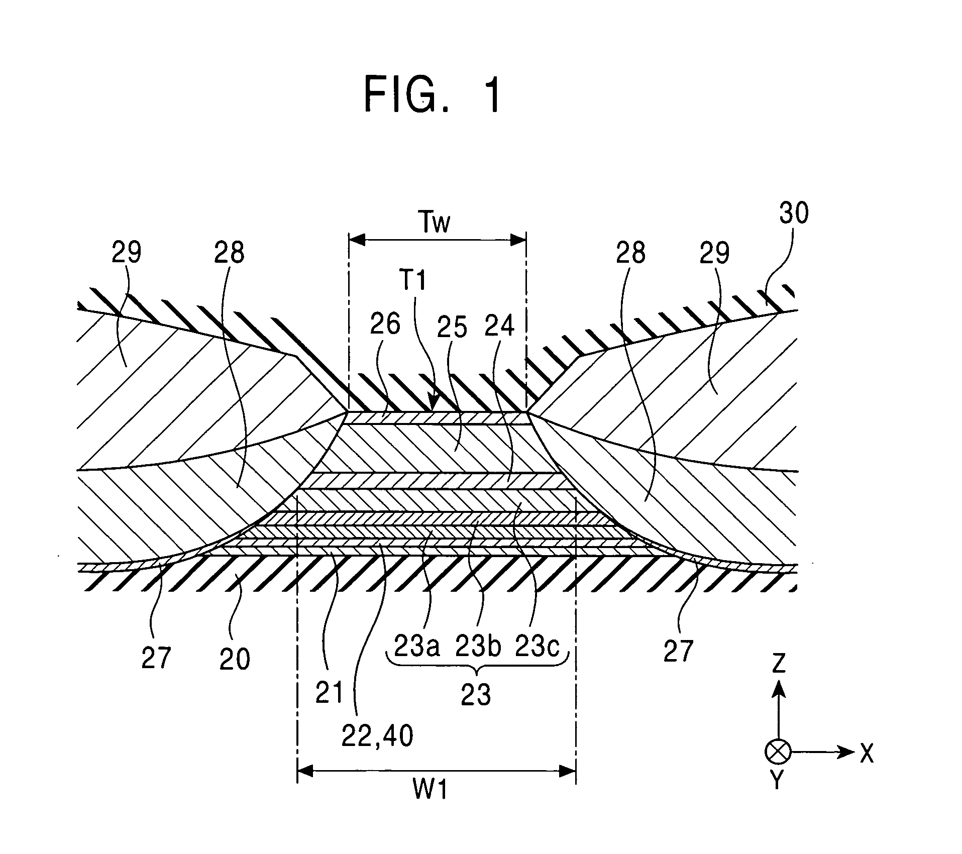
[0210] In this example, by omitting the second magnetic layer, the non-magnetic material layer, the free magnetic layer, and the like, measurement of the magnetostriction of the first magnetic layer 23a was accurately performed.

[0211] For the measurement of the magnetostriction, an optical lever method was used. While the surface of the multilayer film described above was irradiated with laser beams, a magnetic field was applied to the multilayer film in the direction parall...


PUM

PropertyMeasurementUnit
crystal latticeaaaaaaaaaa
widthaaaaaaaaaa

Abstract

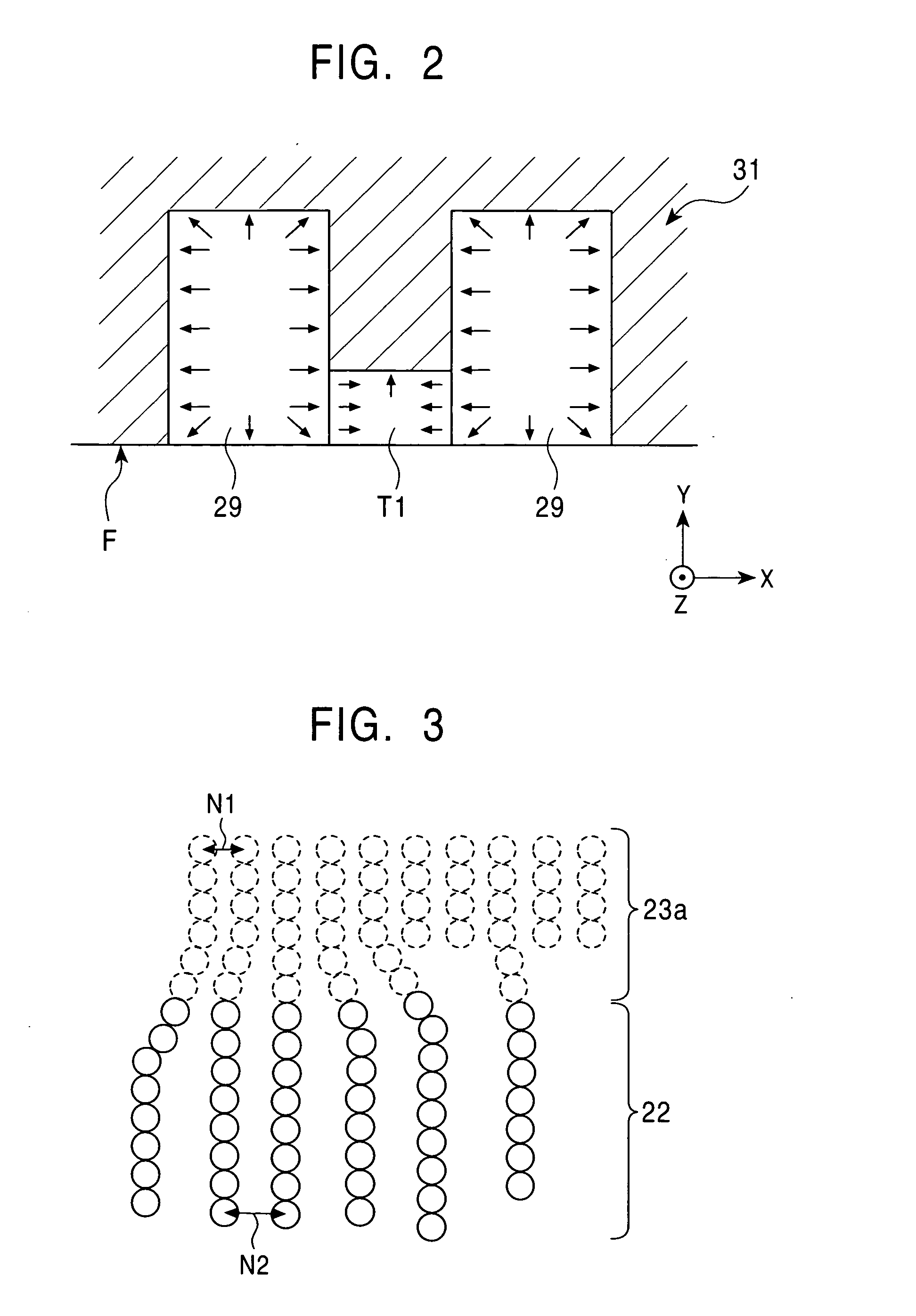
A fixed magnetic layer contains a first magnetic layer formed on a non-magnetic metal layer. The non-magnetic metal layer is composed of an X—Mn alloy (where X is selected from Pt, Pd, Ir, Rh, Ru, Os, Ni, and Fe). While atoms forming the first magnetic layer and atoms forming the non-magnetic metal layer are being aligned with each other, strains are generated in the individual crystal structures. By generating the strain in the crystal structure of the first magnetic layer, the magnetostriction constant λ is increased. As a result, a magnetic sensor having a large magnetoelastic effect can be provided.

Description

[0001] This application is a continuation-in-part of application Ser. No.: 10 / 783,159 which was filed on Feb. 20, 2004 and which claims the benefit of priority to Japanese Patent Application No.: 2003-048694, filed on Feb. 21, 2003, both of said priority applications being herein incorporated by reference in their entirety. This application also claims the benefit of priority to Japanese Patent Application No.: JP2004-049709, which was filed on Feb. 25, 2004, which is incorporated herein in its entirety.BACKGROUND OF THE INVENTION [0002] 1. Field of the Invention [0003] The present invention relates to magnetic sensors each having a free magnetic layer, a non-magnetic material layer, and a fixed magnetic layer, and more particularly, relates to a magnetic sensor fixing the magnetization of a fixed magnetic layer by uniaxial anisotropy thereof. [0004] 2. Description of the Related Art [0005] Among magnetic sensors mounted in magnetic read and write devices, a spin-valve magnetic sens...

Claims


Application Information

Patent Timeline
Patent Type & Authority Applications(United States)
IPC IPC(8): G01R33/09G11B5/39
CPCB82Y25/00G01R33/093Y10T428/1143Y10T29/49034Y10T428/1121G11B5/3906
Inventor HASEGAWA, NAOYAUMETSU, EIJISAITO, MASAMICHIIDE, YOSUKEOSHIMA, MASAHIRO
Owner TDK CORPARATION
Learn More