
System and method of cooling steam turbines

a technology of steam turbines and cooling systems, applied in the direction of liquid fuel engines, liquid degasification, separation processes, etc., can solve the problems of extreme costs, large cooling costs, and high cost, and achieve the effect of reducing downtime and saving costs

Inactive Publication Date: 2005-01-27
BAKER HUGHES INC
View PDF4 Cites 10 Cited by
  • Summary
  • Abstract
  • Description
  • Claims
  • Application Information

AI Technical Summary

Benefits of technology

The present invention offers a cool down method applicable to rotating and moving equipment in the electric power generating industry including steam turbines. By using a flow of nitrogen, preferably a forced flow of nitrogen, the present invention may improve the efficiency of power plant outages by reducing the cool down time associated with large steam turbines. This cool down period can represent a substantial cost if the outage occurs at critical electrical power market conditions. This cost becomes much more substantial and can result in extreme costs if the market conditions increase over $50 per megawatt.
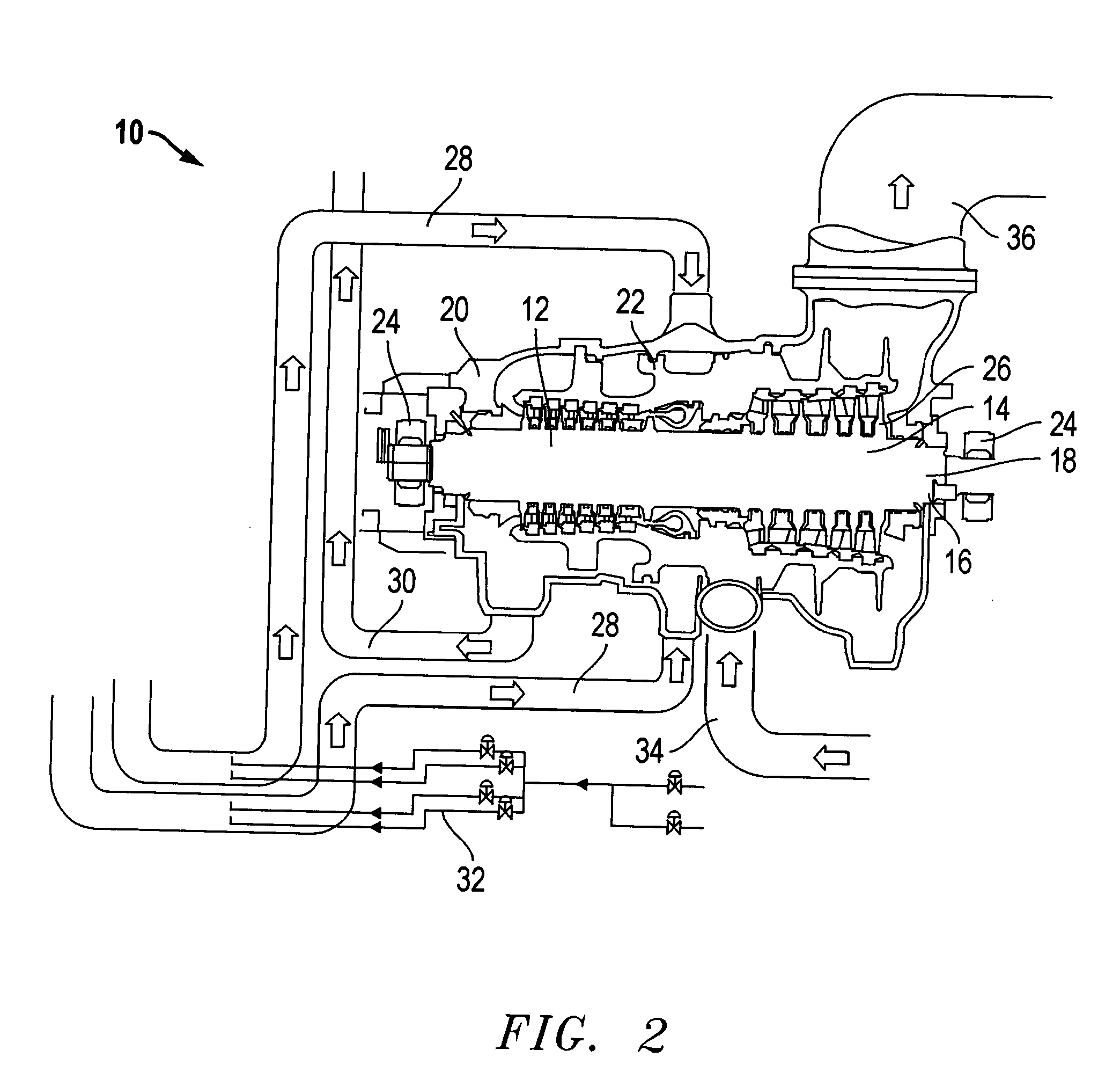
Therefore the different methods discussed herein provide options for applying the nitrogen without damaging the internal, moving components of the turbine by uneven cooling, rapid cooling, or over-spinning. With the nitrogen flow control station, nitrogen can be introduced to different areas of the turbine at different temperatures and / or different flow rates and cooling or heating can be accomplished at different rates in different areas of the turbine so that the machine is cooled down evenly without damage.
Because the clearance tolerance between the casement and the spindle is so tight, the rate of shrinkage of the different parts of the machine is important to the cool down process. Thus the control of the cool down temperatures is significant. It is envisioned that the present invention will be able to reduce the cool down period from the five to eight days of the previous methods to less than approximately two days, preferably less than about 36 hours. This invention also offers a costs saving by providing a quicker shutdown or turnaround time and by extending the production of electricity during the cool down process.
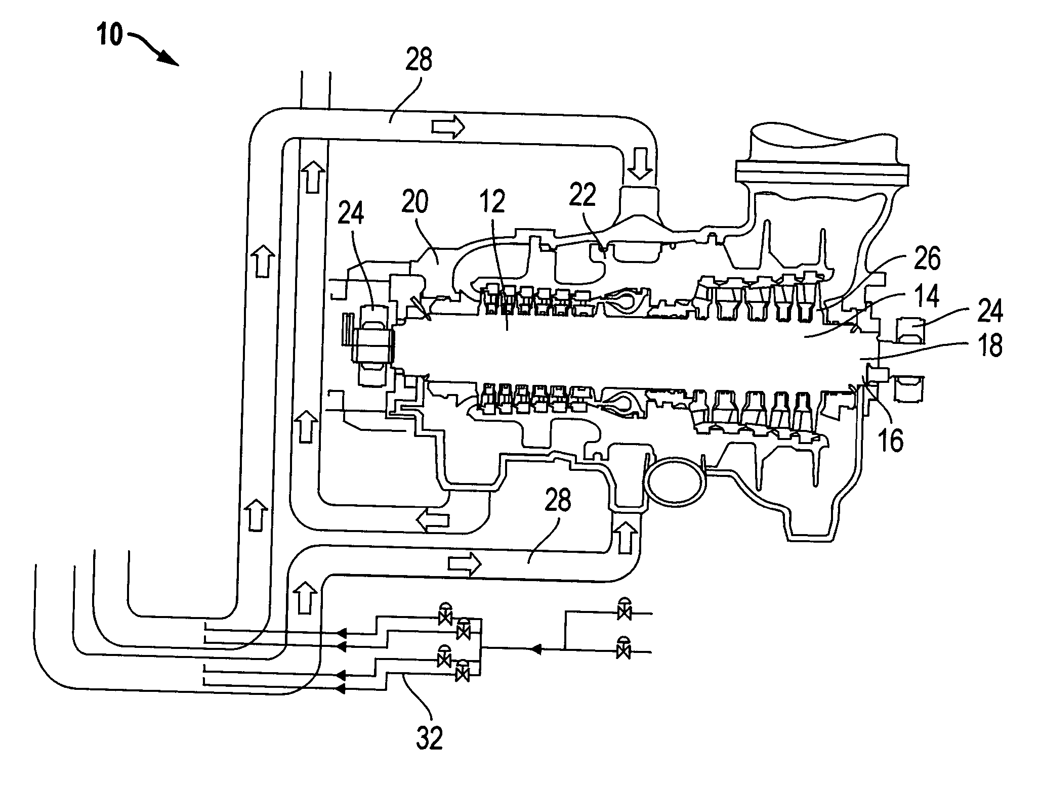
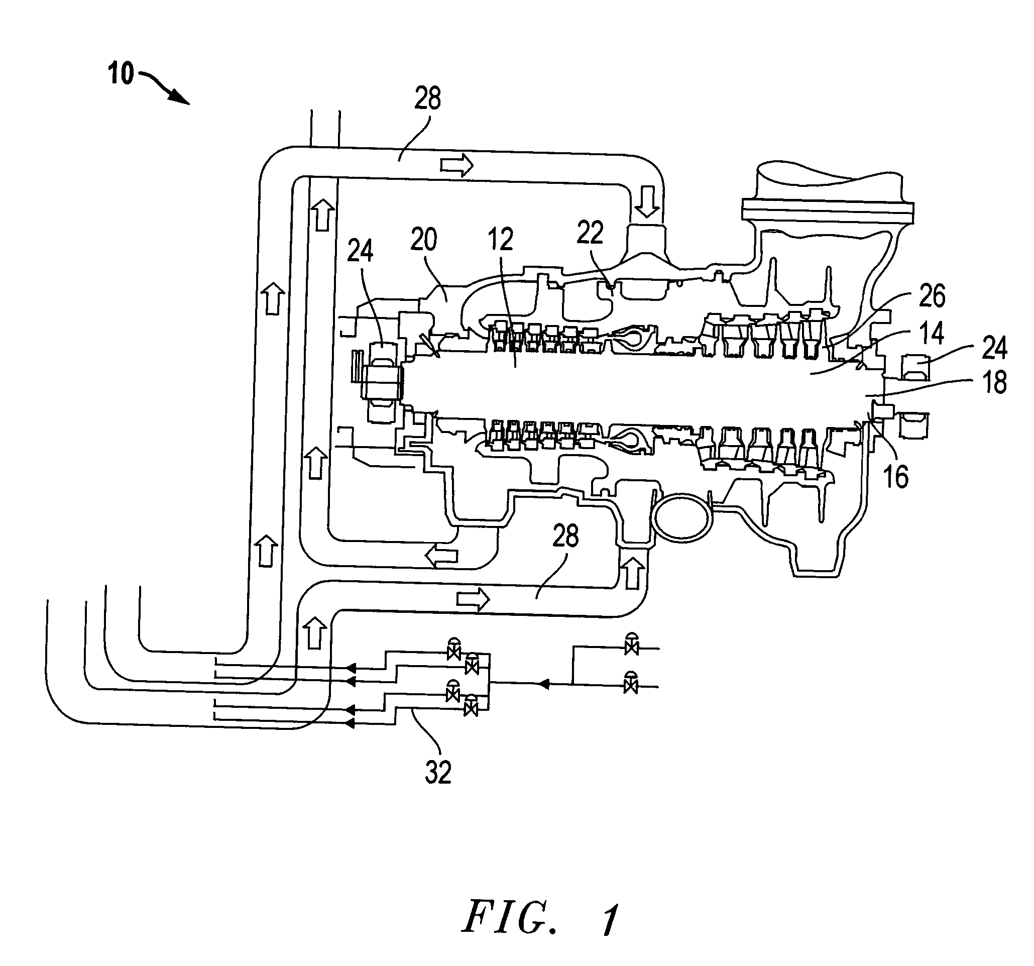
In the preferred embodiment the present invention provides a method of cooling a steam turbine having internal moving components to a predetermined temperature, wherein the steam turbine comprises a main steam inlet piping connected to the turbine and a cold reheat line connected to the turbine such that a flow of steam first moves from the main steam inlet piping to the turbine and then the flow of steam moves from the turbine to the cold reheat line during operation, the method which includes the steps of stopping the flow of steam, introducing a flow of nitrogen to the turbine until the turbine reaches the predetermined temperature while controlling the flow of nitrogen to prevent damage to the moving components of the turbine, and stopping the flow of nitrogen. This method may also include a hot reheat line connected to the turbine and a condenser vacuum relief line connected to the turbine such that a flow of steam first moves from the hot reheat line to the turbine and then the flow of steam moves from the turbine to the condenser vacuum relief line during operation, wherein the flow of nitrogen in also moves from the hot reheat line to the turbine and then the flow of nitrogen moves from the turbine to the condenser vacuum relief line.
This invention also provides for a more efficient and cost effective method of operating a power plant by using the methods listed above to reduce downtime by cooling each steam turbine using the inventive concepts as disclosed and claimed herein.

Problems solved by technology

This cool down period can represent a substantial cost if the outage occurs at critical electrical power market conditions.
This cost becomes much more substantial and can result in extreme costs if the market conditions increase over $50 per megawatt.

Method used


Image

  • System and method of cooling steam turbines
  • System and method of cooling steam turbines
  • System and method of cooling steam turbines

Examples


Embodiment Construction

The present invention offers forced cooling of a flow of nitrogen such that a steam turbine may be cooled in a shorter period of time. In a most preferred embodiment, it is expected that a typical large fossil steam turbine unit between 200 and 850 megawatt (“MW”) may be cooled in less than about 48 hours, more preferably less than about 36 hours, most preferably about 24 hours. In fact, it is envisioned that a cool down could be accomplished in as little as about four to about 15 hours in a most preferred embodiment. The time required is dependent on the overall mass of the turbine and the nitrogen flows that can be obtained. The cooling time will be determined by the difference between the time of operation and the time at which the turbine has cooled down from the range of about 350° F. to about 700° F. to a predetermined temperature such as less than about 100° F. to about 200° F. It is expected that substantial differences between turbine sizes, manufactures and power plant sy...


PUM

PropertyMeasurementUnit
Temperatureaaaaaaaaaa
Flow rateaaaaaaaaaa

Abstract

A system and method of cooling a steam turbine having internal moving components to a predetermined temperature by controlling a flow of nitrogen through the turbine, thus decreasing the downtime associated with maintaining the turbine. This provides a more efficient and cost effective method of operating a power plant.

Description

FIELD OF THE INVENTION This invention relates to the field of maintenance of steam turbines having moving internal components, namely in the power generation industry. BACKGROUND OF THE INVENTION In the power industry, electricity is produced with a spinning turbine that is turned at high speeds to generate electricity. This turbine can be turned by water, by gas, or by high temperature steam. The steam turbine is driven by high temperature steam from a conventional boiler reactor or nuclear reactor at speeds averaging 1800 to 3600 rpm. Many of the modern stream turbines operate at temperature in excess of 1,000° F. Approximately 49 percent of the U.S. power generation in 2003 was coal-fired and 28 percent of the generation from nuclear fuel sources. Both fossil and nuclear steam turbines experience substantial cool down time delays associated with planned major outages, planned minor outages, and unplanned outages. A typical steam turbine requires a minimum of one week to cool d...

Claims


Application Information

Patent Timeline
IPC IPC(8): F01D21/00F01D21/20F01D25/12F02C7/18
CPCF01D21/00F01D21/20Y10S60/912F02C7/18F05D2260/232F01D25/12
Inventor BARBER, STEVEN J.TRYGSTAD, PAUL K.
Owner BAKER HUGHES INC
Learn More